6 DriveProgramming Commands
6 - 38
DriveProgramming User’s Manual (I622-E1)
Example
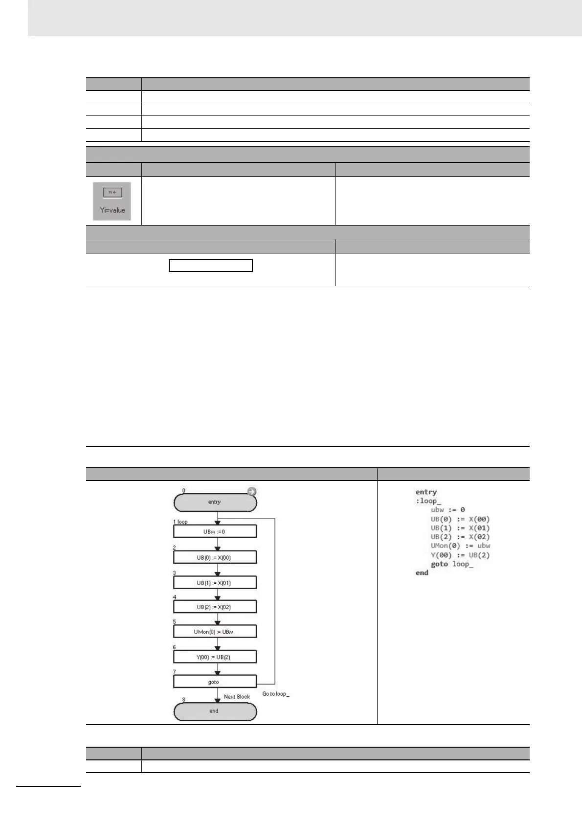
In the above example, the status of X(00) to X(02) is monitored with the parameter UMon(0) (db-08), and X(02) is output to Y(00).
2 Divides the value of U(00) by 4 (2-bit right shift) to assign X(02) to bit 0.
3
Performs a logical AND operation on U(00) and 15 (binary: 00001111) and changes the bits higher than X(06) to zero.
4 Assigns U(00) to Yw.
5 Jumps to the block 1: loop_ unconditionally.
Y(i) = value
Command Description Argument
Outputs data to the output terminal variable in
units of bits.
i: output terminal variable
(range 0 to 6)
Value: any variable or constant
Format
Flowchart method Text language method
↓
Y(i) : = <value>
Note The output terminal variable is a variable that controls the status of the inverter's output termi-
nal. The following settings are required. The numerical order of the output terminal variables
follows the numerical order of the set general-output numbers.
Set the Output Terminal 1 to 5 Selection (CC-01 to CC-05) and the Relay Output (16, AL) Selec-
tion (CC-06, CC-07) to 69 to 75 (MO1 to MO7: General-purpose output).
<Assignment example>
Y(00) = MO1 (General-purpose output 1 No. 69)
Y(01) = MO2 (General-purpose output 2 No. 70)
Y(02) = MO3 (General-purpose output 3 No. 71)
Y(03) = MO4 (General-purpose output 4 No. 72)
Y(04) = MO5 (General-purpose output 5 No. 73)
Y(05) = MO6 (General-purpose output 6 No. 74)
Y(06) = MO7 (General-purpose output 7 No. 75)
For details, refer to 5-2 Input/Output Terminal Variables on page 5-5.
Flowchart Text
Block number
Operation
1 Assigns 0 to UBw.
Block number
Operation

 Loading...


