140
CPU Units Section 3-1
DIP Switch The CJ-series CPU Unit has an 8-pin DIP switch that is used to set basic
operational parameters for the CPU Unit. The DIP switch is located under the
cover of the battery compartment. The DIP switch pin settings are described
in the following table.
Note 1. The following data cannot be overwritten when pin 1 is ON:
• All parts of the user program (programs in all tasks)
• All data in the parameter area (such as the PLC Setup and I/O table)
When pin 1 is ON, the user program and parameter area will not be cleared
when the memory clear operation is performed from a Programming De-
vice.
2. The CPU Unit will not enter any mode except PROGRAM mode after back-
ing up data to a Memory Card using DIP switch pin 7. To enter RUN or
MONITOR mode, turn OFF the power supply, turn OFF pin 7, and then re-
start the PLC. This will enable changing the operating mode as normal.
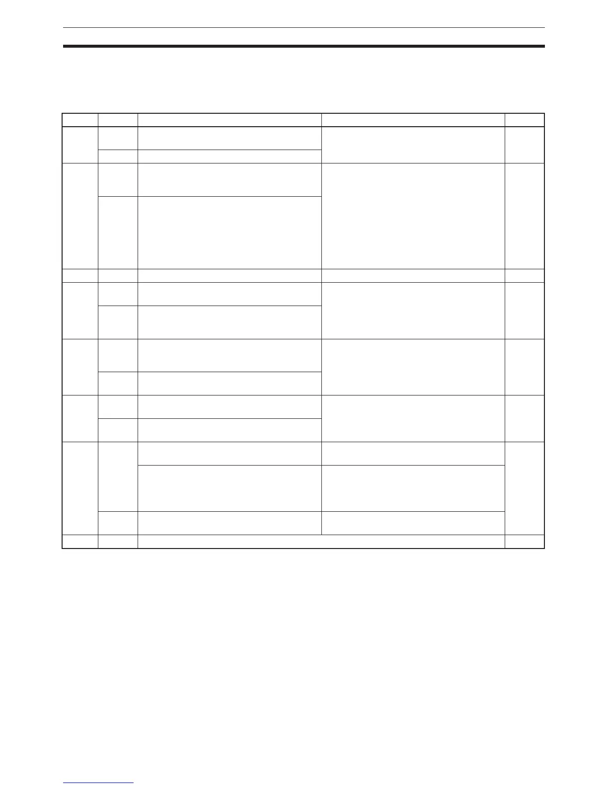
Pin no. Setting Function Usage Default
1 ON Writing disabled for user program memory.
(See note.)
Used to prevent programs from being acci-
dently overwritten from Programming
Devices (including Programming Console).
OFF
OFF Writing enabled for user program memory.
2 ON The user program is automatically trans-
ferred from the Memory Card when power is
turned ON.
Used to store the programs in the Memory
Card to switch operations, or to automatically
transfer programs at power-up (Memory
Card ROM operation).
Note When pin 7 is ON and pin 8 is OFF,
easy backup reading from the Memory
Card is given priority, so even if pin 2 is
ON, the user program is not automati-
cally transferred from the Memory
Card when power is turned ON.
OFF
OFF The user program is not automatically trans-
ferred from the Memory Card when power is
turned ON.
3 --- Not used. --- OFF
4 ON Peripheral port communications parameters
set in the PLC Setup are used.
Turn ON to use the peripheral port for a
device other than Programming Console or
CX-Programmer (Peripheral bus only).
OFF
OFF Peripheral port communications parameters
set using Programming Console or CX-Pro-
grammer (Peripheral bus only) are used.
5 ON RS-232C port communications parameters
set using a CX-Programmer (Peripheral bus
only) are used.
Turn ON to use the RS-232C port for a Pro-
gramming Device.
OFF
OFF RS-232C port communications parameters
set in the PLC Setup are used.
6 ON User-defined pin. Turns OFF the User DIP
Switch Pin Flag (A39512).
Set pin 6 to ON or OFF and use A39512 in
the program to create a user-defined condi-
tion without using an I/O Unit.
OFF
OFF User-defined pin. Turns ON the User DIP
Switch Pin Flag (A39512).
7 ON Writing from the CPU Unit to the Memory
Card.
Press and hold the Memory Card Power
Supply Switch for three seconds.
OFF
Restoring from the Memory Card to the CPU
Unit.
To read from the Memory Card to the CPU
Unit, turn ON the PLC power.
This operation is given priority over automatic
transfer (pin 2 is ON) when power is ON.
OFF Verifying contents of Memory Card. Press and hold the Memory Card Power
Supply Switch for three seconds.
8OFFAlways OFF. OFF
 Loading...


