43
CJ1-H/CJ1M CPU Unit Ver. 2.0 Upgrades Section 1-5
When using communications for to 4 to 8 network levels, use only CS/CJ-
series CPU Units Ver. 2.0 or later. Other CPU Units cannot be used. Rout-
ing errors (error codes 0501 to 0504 hex) may occur in the relaying PLCs,
preventing a FINS response from being returned.
2. With CS/CJ-series CPU Units with unit version 2.0 or later, the Gateway
Counter (GCT: Number of allowed bridge passes) for FINS command/re-
sponse frames is the value decremented from 07 hex (variable). (In earlier
versions, the value was decremented from 02 hex.) With unit version 3.0
or later, the default GCT for FINS command/response frames is the value
decremented from 02 hex. CX-Net can be used to select 07 hex as the val-
ue from which to decrement.
3. Do not use the Gateway Counter (GCT: Number of allowed bridge passes)
enclosed in the FINS header of the FINS command/response frame in ver-
ification checks performed by user applications in host computers. The
GCT in the FINS header is used by the system, and a verification error may
occur if it is used to perform verification checks in user applications, partic-
ularly when using CS/CJ-series CPU Units with unit version 2.0 or later.
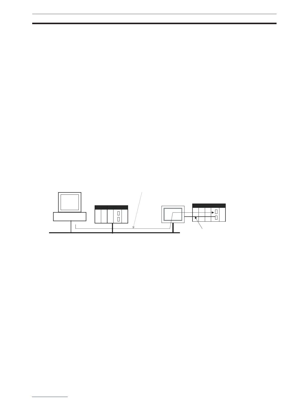
1-5-6 Connecting Online to PLCs via NS-series PTs
Summary The CX-Programmer can be connected online to a PLC connected via a serial
line to an NS-series PT that is connected to the CX-Programmer via Ethernet
(see note 2). This enables uploading, downloading, and monitoring the ladder
program and other data.
Note 1. The NS-series PT must be version 3.0 or higher and the CX-Programmer
must be version 3.1 or higher.
2. Connection is not possible through an NS-series PT connected serially to
the CX-Programmer.
Connection Method In CX-Programmer, open the Change PLC Window and set the Network Type
to Ethernet. Click the Settings Button and set the IP address of the NS-series
PT on the Driver Tab Page. Also make the following settings on the Network
Tab Page.
• FINS Source Address
Set the local network address of the NS-series PT for the Network (exam-
ple network address: 1).
• FINS Destination Address
Network: Set the address to 111 if the PLC is connected to serial port A
on the NS-series PT and to 112 if it is connected to serial port B.
Node: Always set to 1
• Frame Length: 1,000 (See note.)
• Response Timeout: 2
PLC #1
CX-Programmer
(Example IP address: 192.168.0.1)
Ethernet (See note 1.)
(Example network address: 1)
CS/CJ-series
CPU Unit Ver. 2.0
Connect online to PLC #1 to enable
programming, monitoring, and other operations.
NS-series PT
(Example IP address:
192.168.0.22)
1:N NT Link
(Example network address: 111)
 Loading...


