260
Overview Section 6-1
6-1 Overview
There are two kinds of initial settings for a CJ-series PLC: Hardware settings
and software settings. Hardware settings are made with the CPU Unit’s DIP
switch and software settings are made in the PLC Setup (using a Program-
ming Device).
The DIP switch can be reached by opening the battery compartment cover on
the front of the CPU Unit.
Note Before touching or setting the DIP switch while the power is being supplied to
the CPU Unit, always touch a grounded piece of metal to release static elec-
tricity from your body.
Note The display language for the Programming Console is not set on the DIP
switch for CJ-series CPU Units, but rather is set using a Programming Con-
sole key sequence.
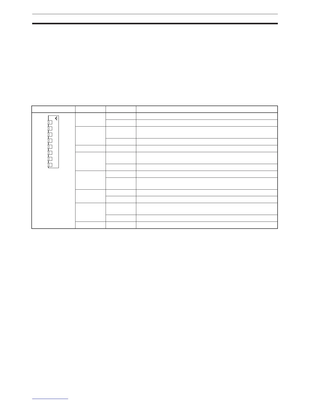
Appearance Pin No. Setting Function
1 ON Writing disabled for user program memory.
OFF Writing enabled for user program memory.
2 ON The user program is automatically transferred when power is turned
ON.
OFF
3 --- Not used.
4 ON Use peripheral port communications parameters set in the PLC
Setup.
OFF Use default peripheral port communications parameters.
5 ON Use default RS-232C port communications parameters.
OFF Use RS-232C port communications parameters set in the PLC
Setup.
6 ON User-defined pin. Turns ON the User DIP Switch Pin Flag (A39512).
OFF User-defined pin. Turns OFF the User DIP Switch Pin Flag (A39512).
7 ON Writing data from the CPU Unit to the Memory Card or restoring data
from the Memory Card to the CPU Unit.
OFF Verifying contents of Memory Card.
8OFFAlways OFF.
1 2 3 4 5 6 7 8
ON