91
CPU Unit Components and Functions Section 2-2
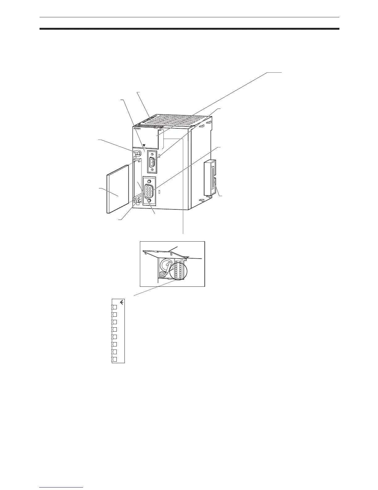
2-2 CPU Unit Components and Functions
2-2-1 CPU Unit Components
PERIFHERAL
E
R
R
/A
L
M
R
U
N
IN
H
C
O
M
M
P
R
P
H
L
C
O
N
T
R
O
L
L
E
R
CJ1G-CPU44
SYSMAC
P
R
O
G
R
AM
M
A
B
L
E
P
O
R
T
O
P
E
N
B
U
S
Y
M
C
P
W
R
8 7 6 5 4 3 2 1
ON
Peripheral Port
Connector
Connected to the next Unit.
Memory Card Eject Button
Press the eject button to
remove the Memory Card
from the CPU Unit.
RS-232C Port
Memory Card
Memory Card
Connector
Connects the Memory
Card to the CPU Unit
LED Indicators
Refer to following table.
Memory Card Indicators
MCPWR (green): Lit when
power is supplied to Memory
Card.
BUSY (orange): Lit when
Memory Card is being
accessed.
Slider
Secures the next Unit.
Inside the battery compartment
DIP Switch
Refer to following table.
Memory Card Power
Supply Switch
Press the power supply switch
to disconnect power before
removing the Memory Card.
Also, press the Memory Card
Power Supply Switch to
perform an easy backup
operation.
Connected to Programming Devices,
such as a Programming Console or
host computers. Refer to 3-1 CPU
Units for details.
Connected to Programming Devices
(excluding Programming Consoles),
Host Computers, general-purpose
external devices, Programmable
Terminals, and other devices. Refer
to 3-1 CPU Units for details.