200
Examples Section 4-2
4. Check that the Power Supply Unit’s POWER indicator is lit.
5. Check that the Programming Console has the following display.
6. Press the password (the Clear and Monitor Keys) and check that the Pro-
gramming Console has the following display.
5. Registering the I/O Tables (If Required)
Registering the I/O tables allocates I/O memory to the Units actually installed
in the PLC. It is not necessary to create I/O tables with CJ-series CPU Units
because by default they will be automatically generated when the CPU Unit is
started. I/O tables can be created by the user to detect mistakes in connected
Units or to enable allocating unused words (such as is possible with CS-
series CPU Units).
Note The user program and parameter area data in CJ1-H and CJ1M CPU Units is
backed up in the internal flash memory. The BKUP indicator will light on the
front of the CPU Unit when the backup operation is in progress. Do not turn
OFF the power supply to the CPU Unit when the BKUP indicator is lit. The
data will not be backed up if power is turned OFF.
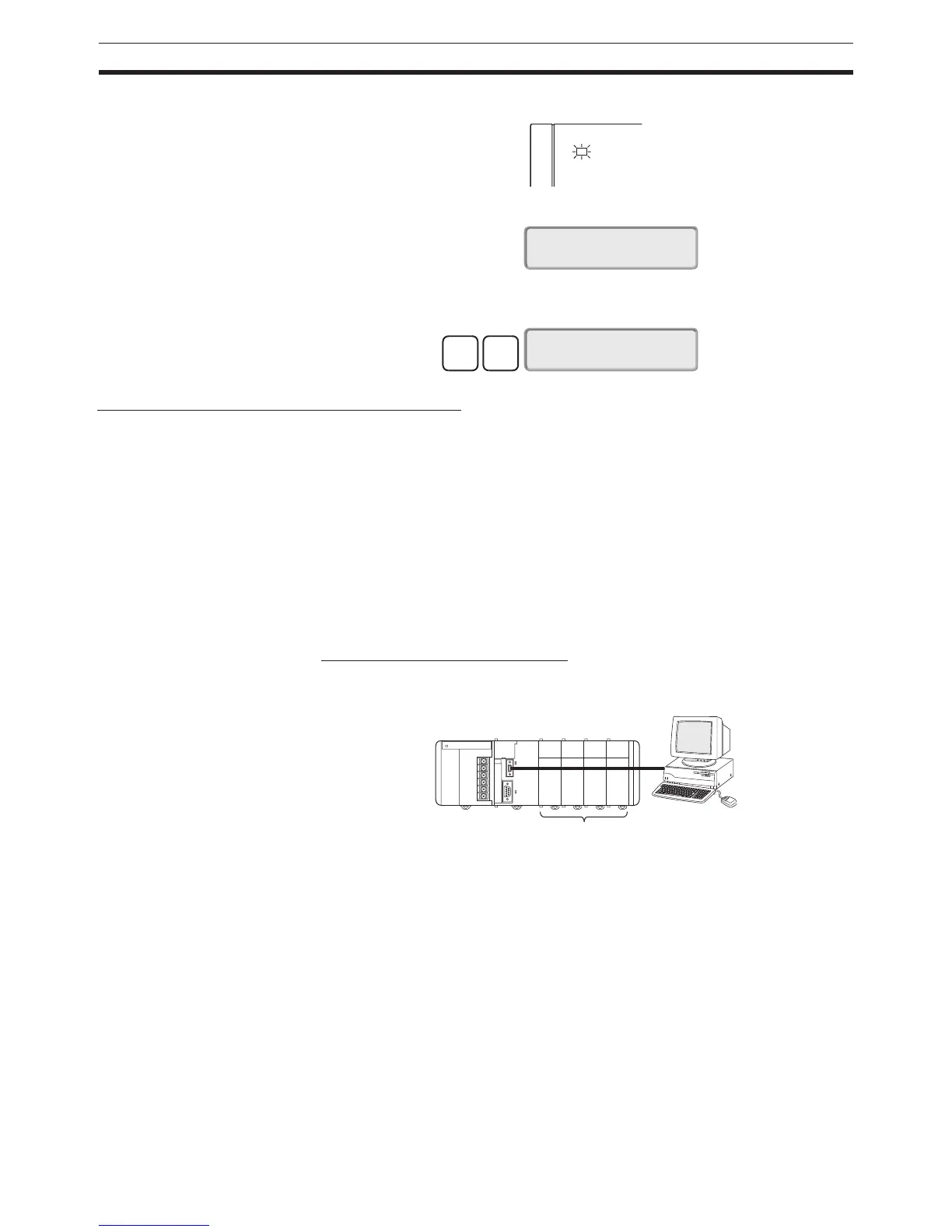
Using the CX-Programmer Online
Use the following procedure to register the I/O table with the CX-Programmer
that is connected to the PLC.
1,2,3... 1. Install all of the Units in the PLC.
2. Connect the CX-Programmer to the peripheral port or RS-232C port.
(The power must be OFF.)
Note If the host computer is being connected to the RS-232C port, pin 5
of the CPU Unit’s DIP switch must be set to ON.
3. Double-click I/O Table on the project tree in the main window. The I/O Ta-
ble Window will be displayed.
4. Select Options and then Create. The models and positions of Units
mounted to the Racks will be written to the Registered I/O Table in the CPU
Unit.
POWER
PA205R
<PRG> 3:JPN~ENG
PASSWORD!
CLR
MON
<PRG> BZ
3:JPN~ENG
N
E
C
PC-9801
B
X
Install the Units.