45
CJ1-H/CJ1M CPU Unit Ver. 2.0 Upgrades Section 1-5
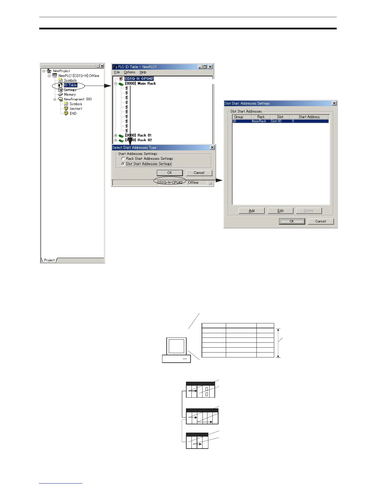
Operating Procedure Select Option - Rack/Slot Start Addresses in the PLC IO Table - Traffic Con-
troller Window. This command will enable setting both the first Rack
addresses and the first slot addresses.
This function can be used, for example to allocate fixed addresses to Input
Units and Output Units. (With CQM1H PLCs, input bits are from IR 000 to
IR 015 and output bits are from IR 100 to IR 115. First slot addresses can be
set when replacing CQM1H PLCs with CS/CJ-series PLCs to reduce conver-
sion work.)
Double-click
Select Option - Rack/Slot Start Addresses.
100
0
102
1
105
5
0
12
01
2
01 2
34
Slot No.
Slot No. 00
Slot No. 02
Slot No. 00
Slot No. 02
Slot No. 00
Slot No. 01
CIO 0005
CIO 0105
CIO 0001
CIO 0102
CIO 0000
CIO 0100
CX-Programmer
Ver. 3.2 or higher
Rack No.
CPU Rack
CPU Rack
Rack 1
Rack 1
Rack 2
Rack 2
Example:
CPU Rack slot
Rack 1 slot
Rack 2 slot
Up to 8 settings
can be made.
First slot addresses