EasyManuals Logo

Omron CJ2M-CPU Series Connection Guide

Omron CJ2M-CPU Series
64 pages
To Next Page IconTo Next Page
To Previous Page IconTo Previous Page
Page #37 background imageLoading...
Page #37 background image
7
Serial Communications Connection Procedure
34
11
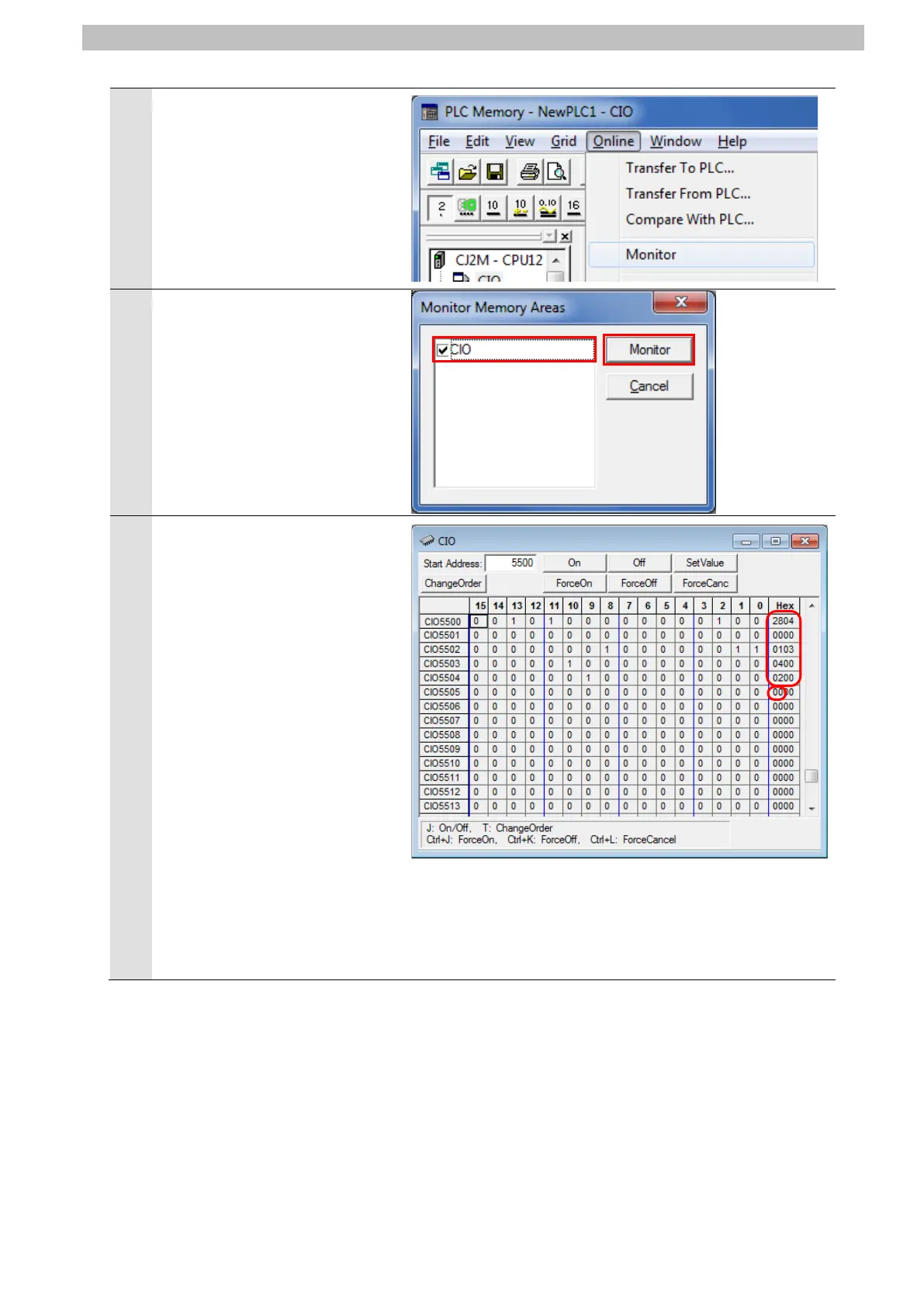
Select Monitor from the Online
Menu.
The Monitor Memory Areas
Dialog Box is displayed.
Select CIO and click Monitor.
Check the received data in the
CIO Window shown on the right.
In the example on the right, the
stored data starting from
CIO5500 are in hexadecimal
and are described as follows:
[2804]: Command code
[0000]: End code
[01]: Driver's address number
[03]: Function code
[04]: Number of bytes to read
[00][02][00][00]: Read data
*The response data differ
depending on the device
intended for use.
*For details, refer to 9.2.2
Detailed Description of the
Function.

Other manuals for Omron CJ2M-CPU Series

Questions and Answers:

Question and Answer IconNeed help?

Do you have a question about the Omron CJ2M-CPU Series and is the answer not in the manual?

Omron CJ2M-CPU Series Specifications

General IconGeneral
Power Supply24 VDC
Number of InstructionsOver 400 instructions
ModelCJ2M-CPU11, CJ2M-CPU12, CJ2M-CPU13, CJ2M-CPU14, CJ2M-CPU15
Program Capacity5K steps to 60K steps
I/O CapacityUp to 2, 560 points
Communication PortsEthernet, USB, RS-232C
Execution Time0.04 µs per basic instruction
Operating Temperature0 to 55°C
Position ControlSupported
High-speed Counter100 kHz max.
Pulse Output100 kHz max.
Maximum Units40 units
Storage Temperature-20 to 75°C
Interrupt InputsSupported

Related product manuals