5 Installation and Wiring
5-18
CP1E CPU Unit Hardware User’s Manual(W479)
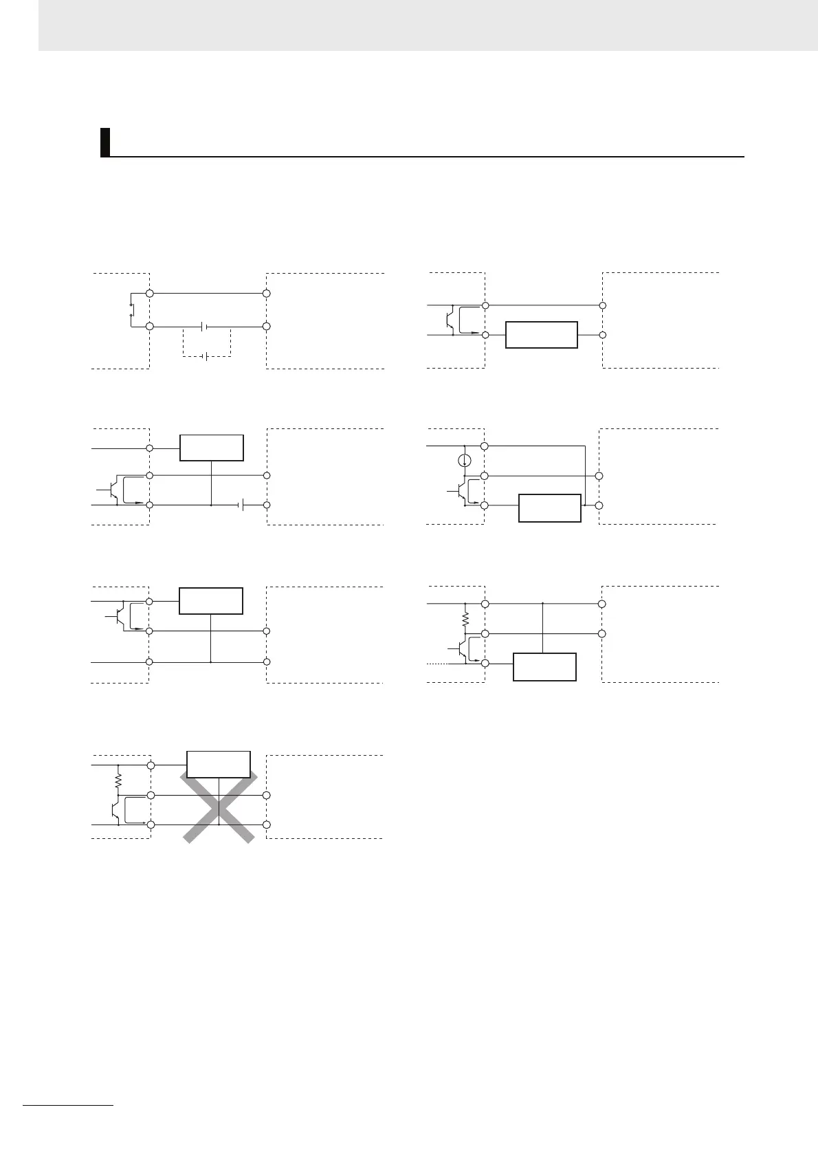
Use the following information for reference when selecting or connecting input devices.
DC Input Units
Connectable DC Input Devices (for DC Output Models)
Example of Input Device Connections
IN
COM
CP1E
Outputs
Outputs
Outputs
Outputs
Outputs
5mA/7.5mA
0V
+
IN
CP1E
5mA/
7.5mA
0V
+
COM
+
IN
COM
CP1E
5mA/7.5mA
0V
+
Two-wire, DC outputs
NPN open-collector outputs
CP1E
COM
IN
Contact outputs
NPN current outputs
Voltage outputs
IN
CP1E
0V
+
COM
IN
COM
CP1E
0V
+
IN
COM
CP1E
+
Sensor power
supply
Sensor power
supply
The circuit below should NOT be used for I/O devices
having a voltage output.
Sensor power
supply
Sensor power
supply
Sensor power
supply
Current
regulator
Sensor power
supply
PNP current outputs
2
2
2
2
1
1
 Loading...


