A-39
Appendices
CP1E CPU Unit Hardware User’s Manual(W479)
A-3 Wiring for Serial Communications
App
A-3-3 Converting the Built-in RS-232C Port to
RS-422A/485
Connection Examples
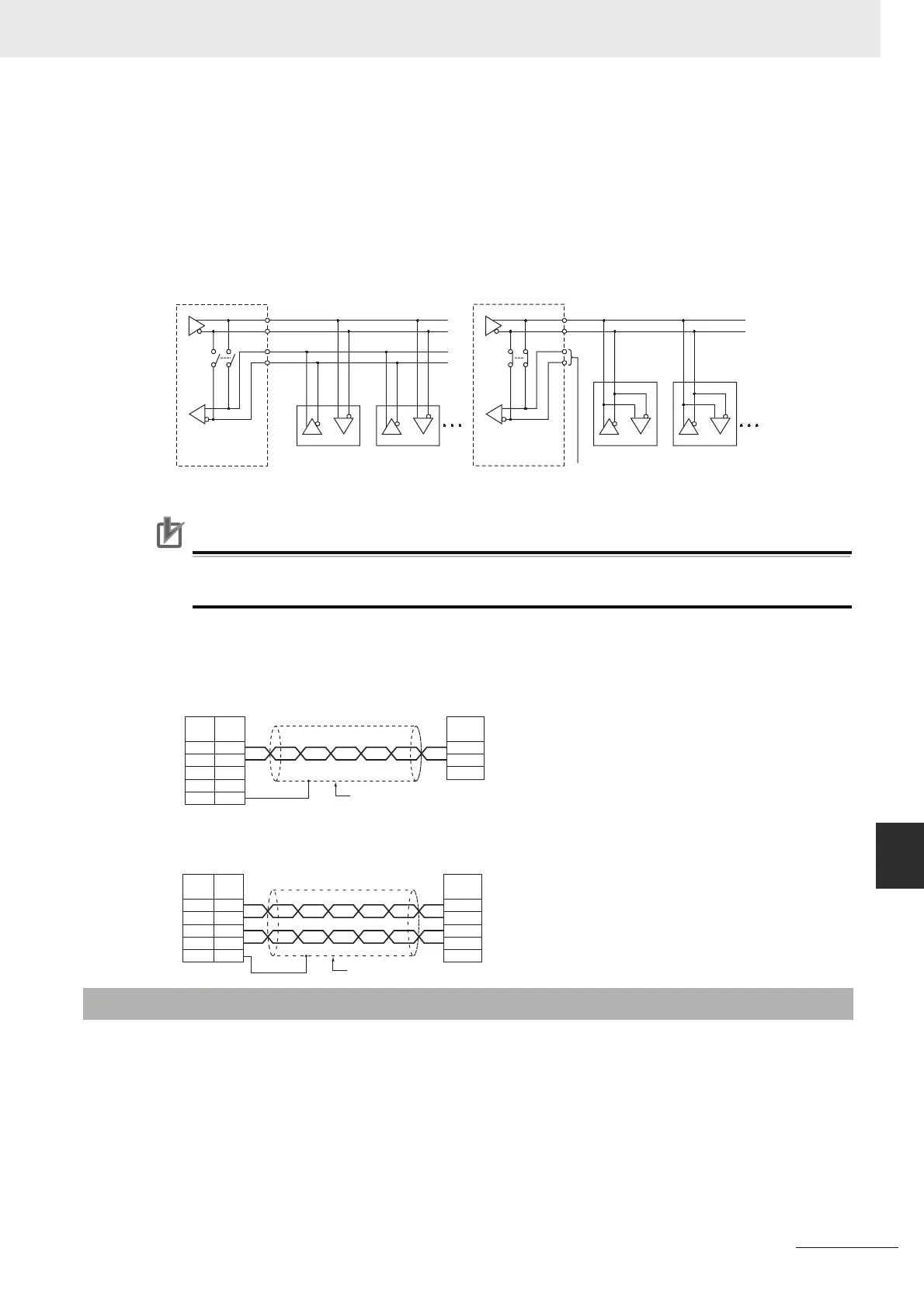
2-Wire and 4-Wire Transmission Circuits
The transmission circuits for 2-wire and 4-wire connections are different, as shown in the following
diagram.
Precautions for Correct UsePrecautions for Correct Use
Use the same type of transmission circuit (2-wire or 4-wire) for all nodes.
Do not use 4-wire connections when the 2/4-wire switch on the Board is set to 2-wire.
Wiring Example: 1:1 Connections
• Two-wire Connections
• Four-wire Connections
Use one of the following Conversion Units to convert a built-in RS-232C port to an RS-422A port for a
CP1E N/NA-type CPU Unit.
• CJ1W-CIF11 RS-422A Conversion Unit
Maximum distance: 50 m, convertible to RS-422A or RS-485.
• NT-AL001 RS-232C/RS-422A Conversion Unit:
Maximum distance: 500 m, convertible to RS-422A only.
A-3-3 Converting the Built-in RS-232C Port to RS-422A/485
Example of 4-Wire Connections
Example of 2-Wire Connections
2/4-wire switch
(DPDT)
O
tion Board
2/4-wire switch
(DPDT)
Option Board
Not connected
Other Unit
Other UnitOther Unit
Other Unit
SDA-
SDB+
RDA-
RDB+
FG
3
4
1
2
5
FG
A(–)
B(+)
CP1E N/NA-type CPU Unit
RS-422A/485 Option Board
Pin Signal
Signal
Shield
Remote device
SDA-
SDB+
RDA-
RDB+
FG
3
4
1
2
5
RDA
RDB
SDA
SDB
FG
CP1E N/NA-type CPU Unit
RS-422A/485 Option Board
Pin Signal Signal
Shield
Remote device