3-11
3 Part Names and Functions
CP1E CPU Unit Hardware User’s Manual(W479)
3-1 CPU Units
3
3-1-3 Common I/O Specifications
*1 The bits that can be used depend on the model of CPU Unit.
*2 The response time is the delay caused by hardware. The delay set in the PLC Setup (0 to 32 ms, default: 8 ms)
for a normal input must be added to this value.
CP1E-DR-
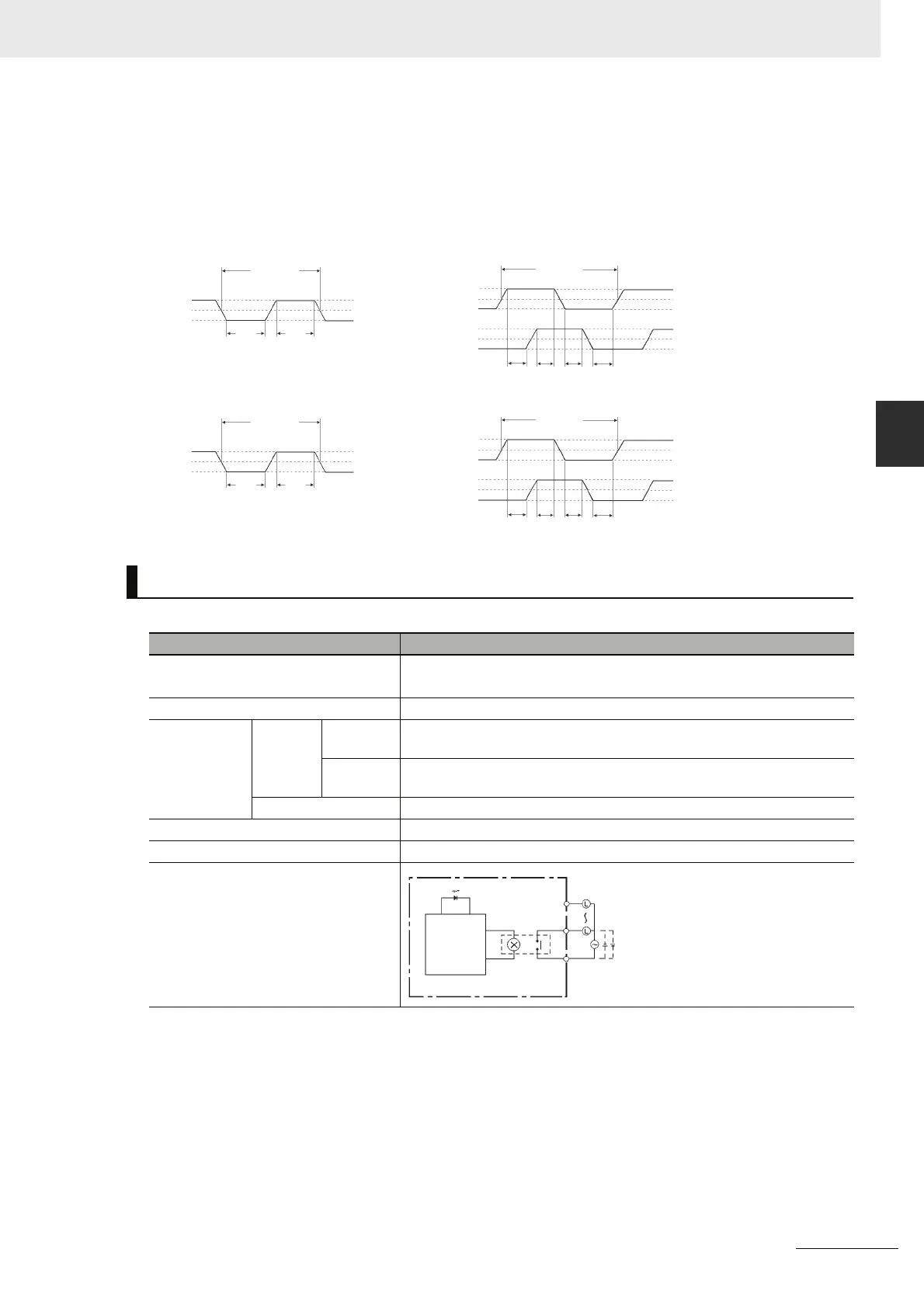
Output Specifications for Relay Outputs
Item Specification
Maximum switching capacity 2 A 250 VAC (cosφ= 1)
2 A 24 VDC (4 A/common)
Minimum switching capacity 10 mA 5 VDC
Service life of
relay
Electrical Resistive
load
200,000 operations (24 VDC)
Inductive
load
70,000 operations (250 VAC, cosφ = 0.4)
Mechanical 20,000,000 operations
ON response time 15 ms max.
OFF response time 15 ms max.
Circuit configuration
ON
OFF
ON
OFF
ON
OFF
T1 T2 T3 T4
T1, T2, T3, T4: 2.5 μs min.
90%
50%
10%
90%
50%
10%
90%
50%
10%
2.5μs
min.
2.5μs
min.
20.0μs min.
10.0μs min.
Up/down input mode
Differential phase mode
Pulse plus direction input mode,
Increment mode
N/NA-type: 0.00/0.01 N/NA-type: 0.00/0.01
ON
OFF
ON
OFF
ON
OFF
T1 T2 T3 T4
T1, T2, T3, T4: 50 μs min.
90%
50%
10%
90%
50%
10%
90%
50%
10%
50μs
min.
50μs
min.
200μs min.
100μs min.
E-type: 0.00 to 0.07
N/NA-type: 0.02 to 0.07
E-type: 0.00 to 0.03
N/NA-type: 0.02/0.03
Output indicator
Internal
circuits
COM
OUT
OUT
250 VAC, 2A,
24 VDC, 2 A
max.