6-3SectionHandling
151
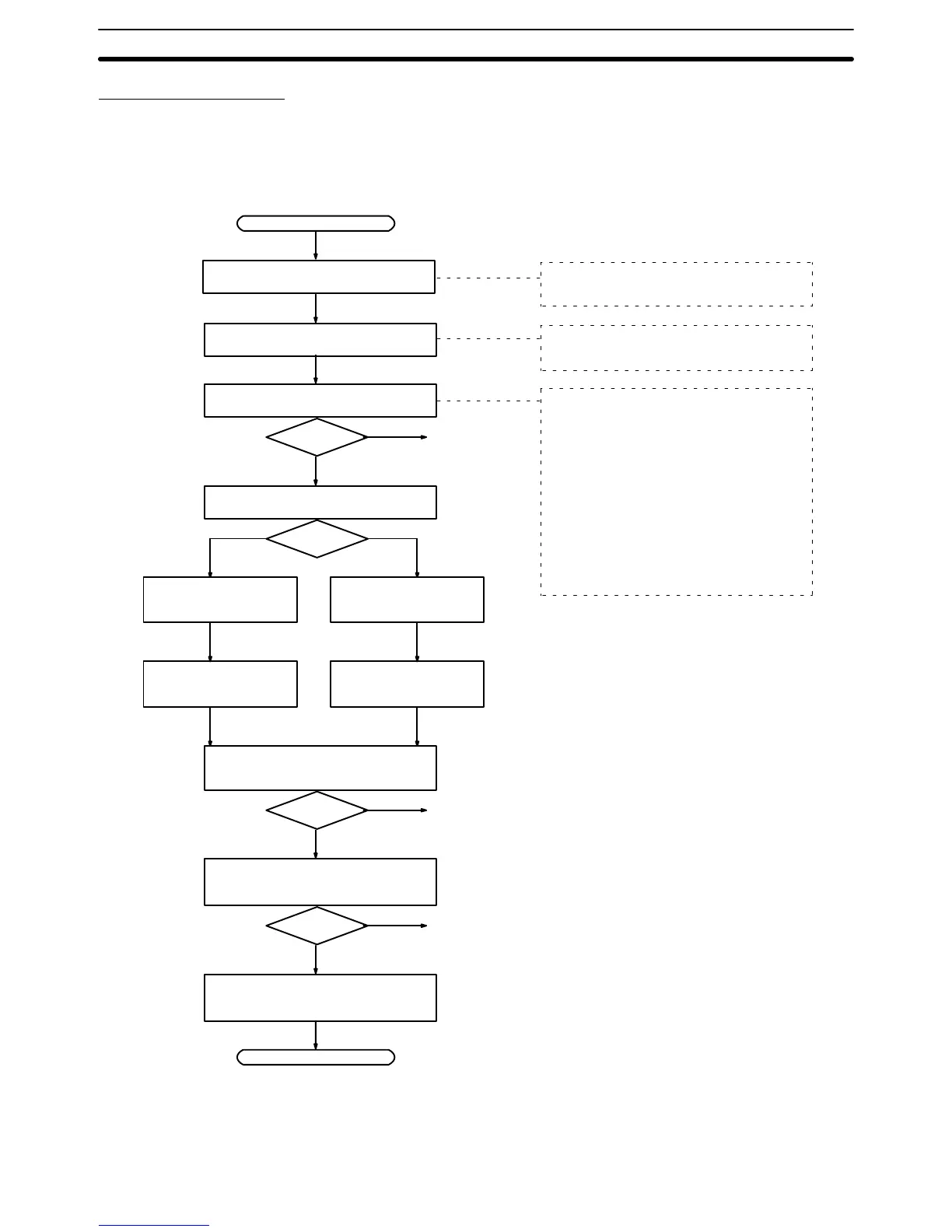
Operation Procedure
Start
Yes
No
Connect the CPM1-EMU01-V1 to the
PC’s peripheral port.
Mount the EEPROM to the
CPM1-EMU01-V1.
After 2 or 3 s, check if the indicator is
lit green.
See the note
on the right.
Select the memory area to be uploaded.
Press the UPLOAD+DM
Button.
Press the UPLOAD But-
ton.
Check if the indicator is blinking green
(indicating that uploading has started).
Yes
No
See the note above.
Check if the indicator is lit green (in-
dicating that uploading has been suc-
cessfully completed).
Yes
No
See the note above.
Remove the Expansion Memory Unit
from the PC.
End
Mount the EEPROM to the CPM1-EMU01-V1
before connecting to the PC.
Check the orientation of the connector
before connecting the CPM1-EMU01-V1.
Note If the indicator is not lit at all, lit red or
blinks red, uploading will not be pos-
sible. In this case, check the follow-
ing items.
• Is the connector properly con-
nected?
• Is the EEPROM properly mounted?
• Are the EEPROM specifications cor-
rect?
• Are the peripheral port communica-
tions settings correct?
Upload both the ladder
program and DM 6144 to
DM 6655.
Upload only the ladder
program.
 Loading...


