38
CPU Unit Component Descriptions
1, 2, 3... 1. Power Supply Input Terminals
Connect the power supply (100 to 240 VAC or 24 VDC) to these terminals.
2. Functional Ground Terminal (
)
Be sure to ground this terminal (AC-type PCs only) to enhance immunity to
noise and reduce the risk of electric shock.
3. Protective Ground Terminal (
)
Be sure to ground this terminal to reduce the risk of electric shock.
4. External Power Supply Terminals
CPM2A PCs are equipped with these 24-VDC power output terminals to
supply power to input devices. (AC-type PCs only.)
5. Input Terminals
Connects the CPU Unit to external input devices.
6. Output Terminals
Connects the CPU Unit to external output devices.
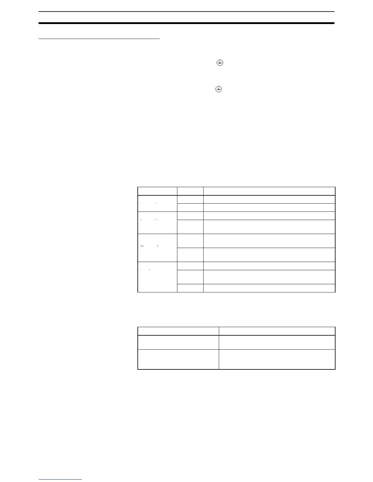
7. PC Status Indicators
These indicators show the operating status of the PC, as shown in the fol-
lowing table.
Indicator Status Meaning
PWR
ON The PC is operating in RUN or MONITOR mode.
(green)
OFF The PC is in PROGRAM mode or a fatal error has
occurred.
COMM
(yellow)
Flashing Data is being transferred via the Peripheral port or
RS-232C port.
ON A fatal error has occurred. (PC operation stops.)
(red)
Flashing A non-fatal error has occurred. (PC operation
continues.)
OFF Indicates normal operation.
8. Input Indicators
The input indicators are lit when the corresponding input terminal is ON. The
indicators are lit during I/O refreshing.
When a fatal error occurs, the input indicators change as follows:
Fatal error Input indicators
CPU Unit error, I/O bus error,
or too many I/O Units
Turn OFF.
Memory error or FALS (fatal
system) error
The indicators will change with the status of
the input signal, but input status will not be
updated in memory.
Note a) When interrupt inputs are used in interrupt input mode, the indica-
tor may not light even when the interrupt condition is met if the in-
put is not ON long enough.
b) When high-speed counters are used, the input indicator may not
light if the input pulse is too fast.
9. Output Indicators
The output indicators are lit when the corresponding output terminal is ON.
The indicators are lit during I/O refreshing. When pulse outputs are being
used, the indicator will remain lit continuously while the pulses are being out-
put.
Unit Components
Section 2-2