51
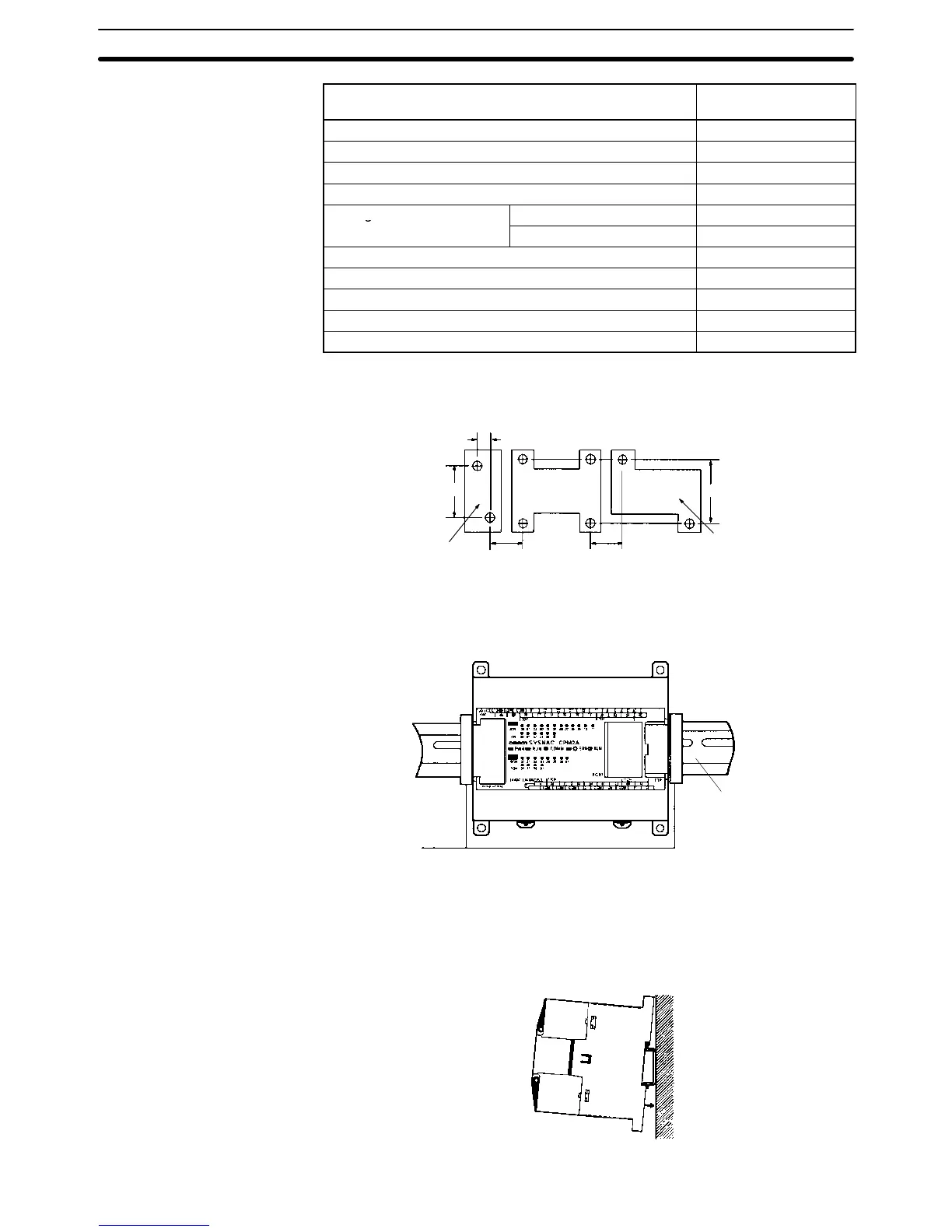
Unit Width (A)
(tolerance: ±0.2 mm)
CPU Unit with 60 I/O terminals 185 mm
Expansion I/O Unit with 20 I/O terminals 76 mm
Expansion I/O Unit with 8 input terminals 56 mm
Expansion I/O Unit with 8 output terminals 56 mm
Analog I/O Unit
MAD01 56 mm
MAD11 76 mm
CompoBus/S I/O Link Unit 56 mm
RS-232C Adapter 21 mm
RS-422 Adapter 21 mm
Temperature Sensor Unit 76 mm
DeviceNet I/O Link Unit 56 mm
Allow 10 to 15 mm between the Units when installing an Expansion Unit, Expan-
sion I/O Unit, or Communications Adapter next to the CPU Unit.
Expansion Unit
or Expansion I/O
Unit
Communications
Adapter
CPU Unit
10 to
15 mm
10 to
15 mm
100 mm
81 mm
21 mm
DIN Track Installation The CPM2A can be installed on a 35-mm DIN Track.
End Plates
(PFP-M)
DIN Track
PFP-100N (1 m)
PFP-50N (50 cm)
PFP-100N2 (1 m)
Installation
Lower the CPM2A so that the notch on the back of the PC catches the top of the
DIN Track. Push the PC forward until the lock snaps into place.
Installing the CPM2A
Section 3-3