114
Adjusting Offset and Gain Section 3-7
!Caution Set the PLC to PROGRAM mode when using the Analog Input Unit in adjust-
ment mode. If the PLC is in MONITOR mode or RUN mode, the Analog Input
Unit will stop operating, and the input values that existed immediately before
this stoppage will be retained.
!Caution Always perform adjustments in conjunction with offset and gain adjustments.
Note Input adjustments can be performed more accurately in conjunction with
mean value processing.
3-7-2 Input Offset and Gain Adjustment Procedures
Specifying Input Number
to be Adjusted
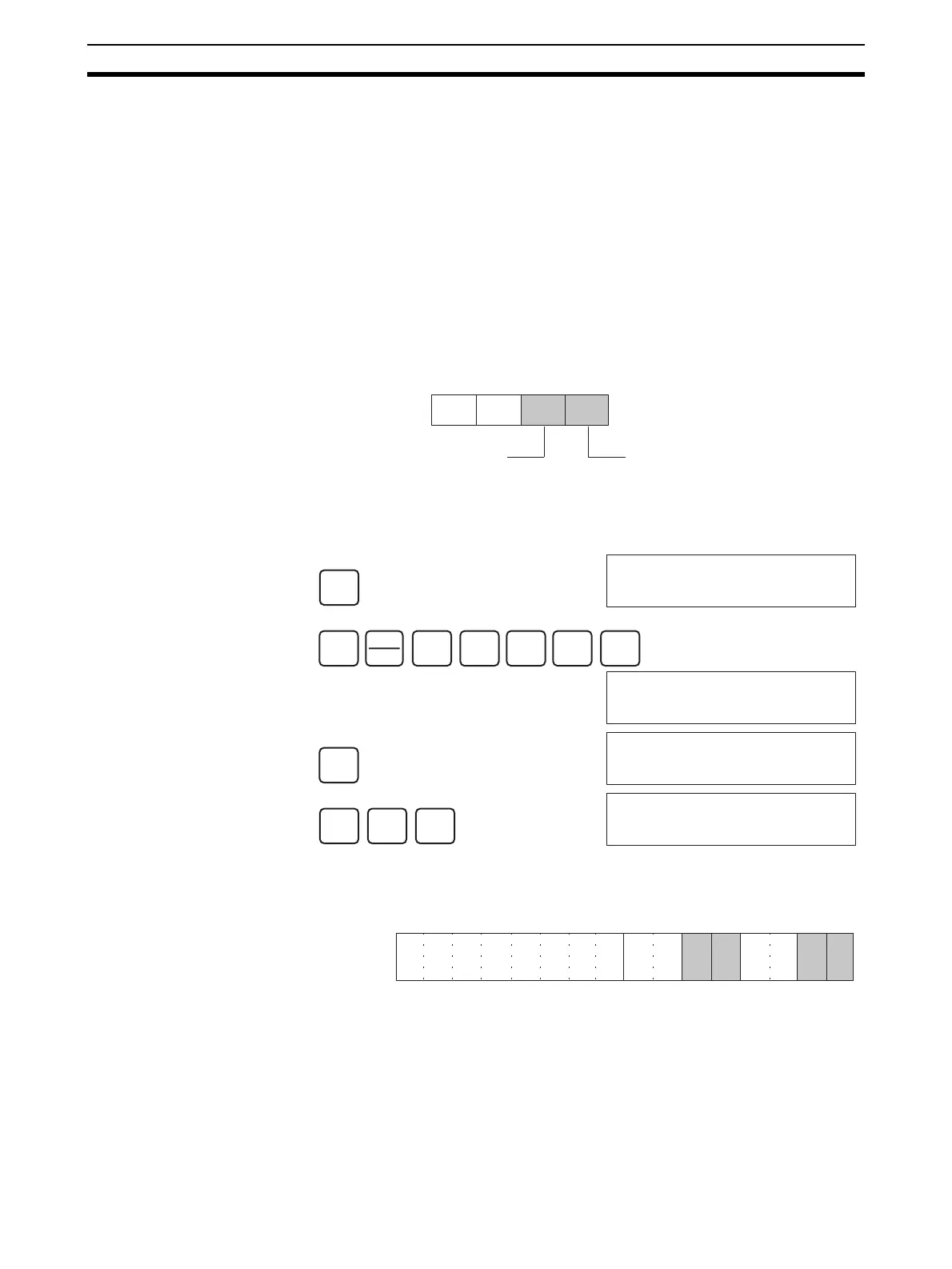
To specify the input number to be adjusted, write the value to the rightmost
byte of CIO word n as shown in the following diagram.
For the CIO word addresses, n = CIO 2000 + (unit number x 10).
The following example uses input number 1 adjustment for illustration. (The
unit number is 0.)
Bits Used for Adjusting
Offset and Gain
The CIO word (n+1) bits shown in the following diagram are used for adjusting
offset and gain.
(Rightmost)
(Leftmost)
Word n
Input to be adjusted (1 to 8)
I/O specification
2: Input (fixed)
(1 to 4 for CS1W-AD041-V1)
CLR
000000 CT00
SHIFT
CH
*DM
2
C
0
A
0
A
0
A
MON
2000 0000
CHG
2000 0000
PRES VAL ????
2
C
1
B
WRITE
2000 0021
15 14 13 12 11 10 09 08 07 06 05 04 03 02 01 00
Bit
Word n+1
Clear Bit
Set Bit
Gain Bit
Offset Bit

 Loading...


