52
Analog Input Functions and Operating Procedures Section 2-6
2-6 Analog Input Functions and Operating Procedures
2-6-1 Input Settings and Conversion Values
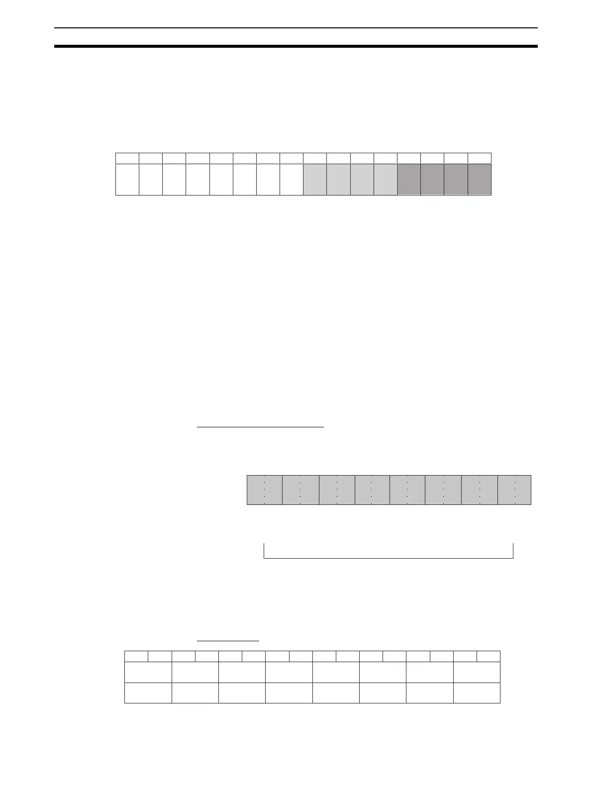
Input Numbers The Analog Input Unit converts analog inputs specified by input numbers. To
specify the analog inputs to be used, turn ON from a Programming Device the
D(m) bits in the DM Area shown in the following diagram.
Setting 0: Not used.
1: Used
• CS1W-AD041-V1: Inputs 1 to 4
• CS1W-AD081-V1: Inputs 1 to 8
The analog input sampling interval can be shortened by setting any unused
input numbers to 0.
Sampling interval = (1 ms) x (Number of inputs used) (See note.)
Note Use 250
µs instead of 1 ms is set to a conversion time of 250 µs and
resolution of 8,000.
The conversion values in words for inputs that have been set to “Not used” will
always be “0000.”
For the DM word addresses, m = D20000 + (unit number x 100)
Input Signal Range Any of four types of input signal range (–10 to 10 V, 0 to 10 V, 1 to 5 V, and 4
to 20 mA) can be selected for each of the inputs.
CS1W-AD041-V1/AD081-V1
To specify the input signal range for each input, set from a Programming
Device the D(m + 1) bits in the DM Area as shown in the following diagram.
Note There are only four inputs for the CS1W-AD041-V1.
CS1W-AD161
D(m)
Bit15141312111009080706050403020100
m = D20000 + unit number x 100
Input 2
Input 1
Input 4
Input 3
Input 6
Input 5
Input 8
Input 7
Input 10
Input 9
Input 12
Input 11
Input 14
Input 13
Input 16
Input 15
15 14 13 12 11 10 09 08 07 06 05 04 03 02 01 00
Bit
DM (m+1)
Input 2
Input 1
00: −10 to 10 V
01: 0 to 10 V
10: 1 to 5 V / 4 to 20 mA
11: 0 to 5 V
Input 4
Input 3
Input 6
Input 5
Input 8
Input 7
Bit
15 14 13 12 11 10 09 08 07 06 05 04 03 02 01 00
D (m+1)
Input 8 Input 6 Input 6 Input 5 Input 4 Input 3 Input 2 Input 1
D (m+2) Input 16 Input 15 Input 14 Input 13 Input 12 Input 11 Input 10 Input 9
m = D20000 + unit number x 100

 Loading...


