182
Components and Switch Settings Section 5-3
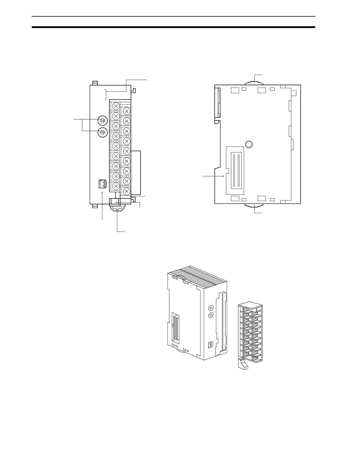
5-3 Components and Switch Settings
The terminal block is attached by a connector. It can be removed by pressing
down on the lever at the bottom of the terminal block. Be sure that this lever is
raised during normal operation.
MACH
No.
DA041
RUN
ERC
ERH
B1 A1
ADJ
x10
1
x10
0
0
9
8
7
6
5
4
3
2
1
0
9
8
7
6
5
4
3
2
1
O
N
12
MODE
With Terminal Block
Indicators
Terminal block lock lever
(pull down to release
terminal block)
DIN Track mounting pin
Operating mode switch
(Not applicable to
DA08V.)
Unit number
switches
Front Side
Slider
Slider
Expansion connector
Terminal block
CJ1W-DA021
CJ1W-DA041
CJ1W-DA08V
CJ1W-DA08C
B1 A1
DA041
M
A
C
H
N
o
.
1
0
1
1
0
0
R
U
N
E
R
C
ER
H
AD
J
M
O
DE
12

 Loading...


