353
Handling Errors and Alarms Section 7-10
7-10-2 Alarms Occurring at the Analog I/O Unit
When an alarm occurs at the Analog I/O Unit, the ERC indicator lights and the
Alarm Flags are stored in bits 08 to 15 of CIO word n+9.
ERC and RUN Indicators: Lit
The ERC and RUN indicators will be lit when an error occurs while the Unit is
operating normally. The following alarm flags will turn ON in CIO word n+9.
These alarm flags will turn OFF automatically when the error is cleared.
Note Disconnection detection operates for input numbers used with a range of 1 to
5 V (4 to 20 mA).
For the CIO word addresses, n = CIO 2000 + (unit number x 10).
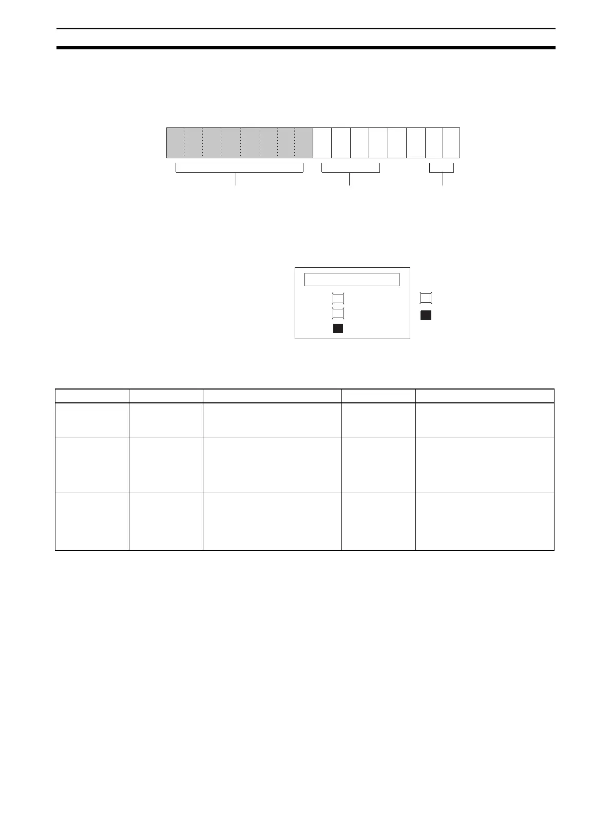
Word n+9
Output setting errorsAlarm Flags
15 14 13 12 11 10 09 08 07 06 05 04 03 02 01 00Bit
Disconnection
Detection Flags
(See 7-6-6 Input
Disconnection
Detection Function.)
(See
7-7-5 Output
Setting Errors
.)
RUN
ERC
ERH
: Lit
: Not li
Word n + 9 Alarm flag Error contents I/O status Countermeasure
Bits 00 and 01 Output Set
Value Error
The output setting range has
been exceeded.
Output value set
by output hold
function.
Correct the set value.
Bits 04 to 07 Disconnection
Detection
A disconnection was detected.
(See note.)
Conversion data
becomes 0000.
Check the rightmost byte of CIO
word n+9. The inputs for bits
that are ON may be discon-
nected. Restore any discon-
nected inputs.
Bit 14 (Adjustment
mode)
EEPROM Writ-
ing Error
An EEPROM writing error has
occurred while in adjustment
mode.
Holds the out-
put status imme-
diately prior to
the error.
Turn the Set Bit OFF, ON, and
OFF again.
If the error persists even after
the reset, replace the Analog I/O
Unit.

 Loading...


