69
Handling Errors and Alarms Section 2-8
While the Clear Bit is ON, the adjusted value will be cleared and reset to
the default offset and gain values when the Set Bit turns ON.
3. To finish the clearing of adjusted values, turn OFF bit 05 (the Clear Bit) of
CIO word n+1.
!Caution Do not turn OFF the power supply or restart the Unit while the Set Bit is ON
(data is being written to the EEPROM). Otherwise, illegal data may be written
in the Unit’s EEPROM and “EEPROM Errors” may occur when the power sup-
ply is turned ON or when the Unit is restarted, causing a malfunction.
!Caution When making adjustments, be sure to perform both the offset adjustment and
gain adjustment at the same time.
Note The EEPROM can be overwritten 50,000 times.
2-8 Handling Errors and Alarms
2-8-1 Indicators and Error Flowchart
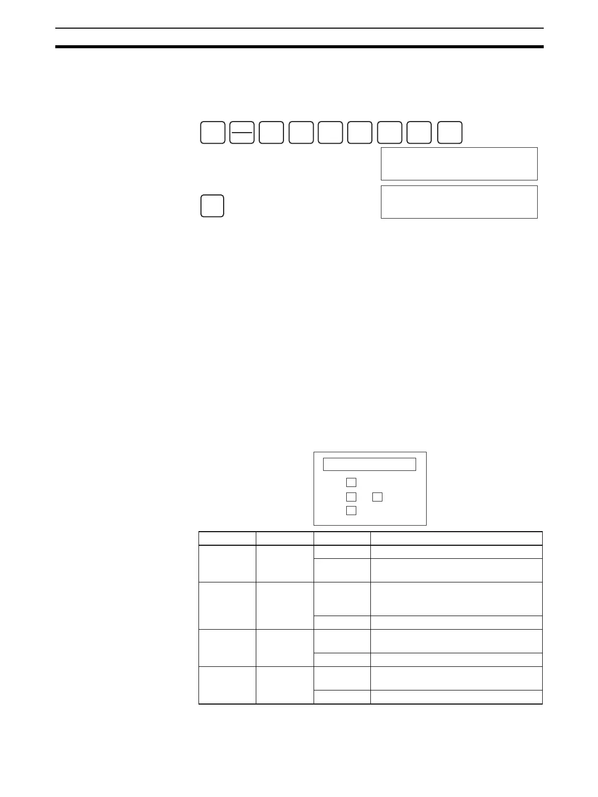
Indicators If an alarm or error occurs in the Analog Input Unit, the ERC or ERH indica-
tors on the front panel of the Unit will light.
SHIFT
CONT
#
2
C
0
A
0
A
1
B
0
A
5
F
MON
200105 ^ ON
RESET
200105 ^ OFF
LED Meaning Indicator Operating status
RUN (green) Operating Lit Operating in normal mode.
Not lit Unit has stopped exchanging data with
the CPU Unit.
ERC (red) Unit has
detected an
error
Lit Alarm has occurred (such as disconnec-
tion detection) or initial settings are incor-
rect.
Not lit Operating normally.
ADJ (yellow) Adjusting Flashing Operating in offset/gain adjustment
mode.
Not lit Other than the above.
ERH (red) Error in the
CPU Unit
Lit Error has occurred during data exchange
with the CPU Unit.
Not lit Operating normally.
Front panel of Unit
RUN
ERC
ADJ
ERH

 Loading...


