368
Sample Programs Appendix B
Note The value scaled using SCL2(486) is stored as positive or negative BCD data according to the status of
the CY (Carry) Flag. To convert the BCD data into signed binary data, use the SCL3(487) instruction.
DM Area Settings
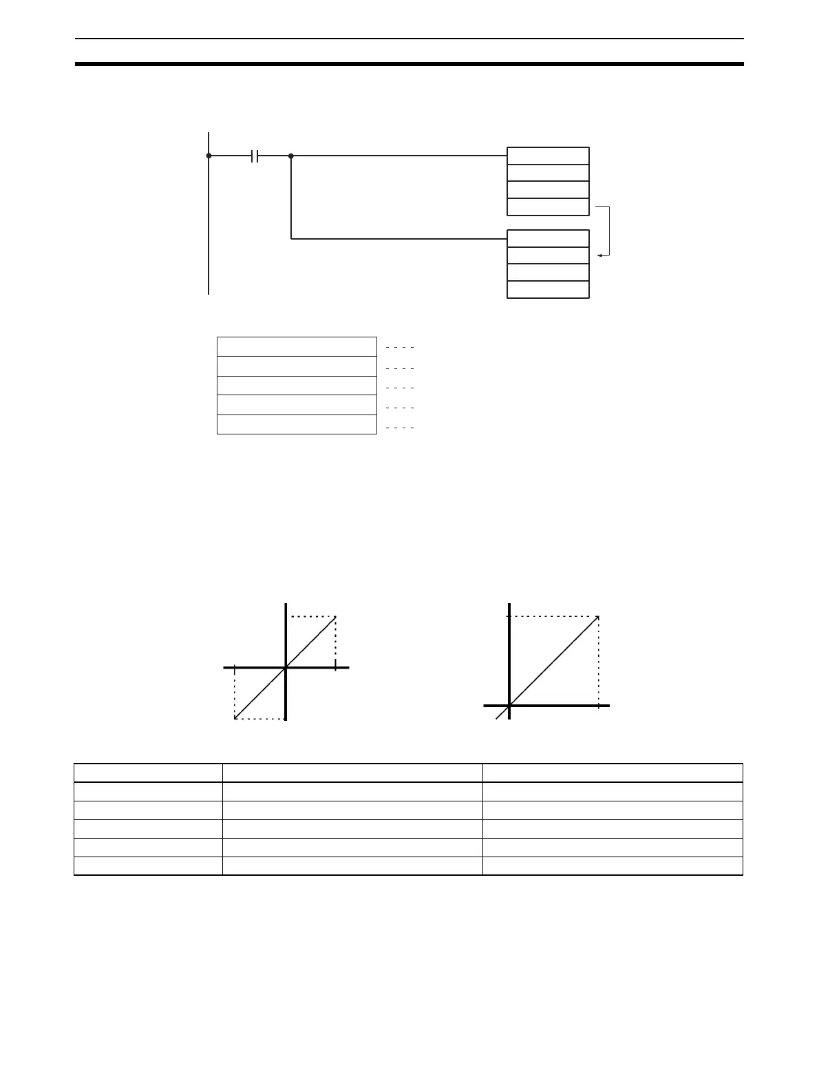
Signed Binary-to-Signed BCD Conversion
A/D conversion values (16-bit binary data) are recognized as 4-digit signed binary data, and converted into 8-
digit signed BCD data. When the leftmost bit is 1, the binary data is recognized as a two’s complement. The
“signed BCD” data refers to BCD data that is indicated by 7-digit data and 1-digit sign (0: +; F: –).
• Conversion Graph (Horizontal Axis: Input Voltage, Vertical Axis: BCD Data)
Unit Settings
SCL2
2005
D00100
D00200
SCL3
D00200
D00300
D00400
Execution condition
D00300: 0000
D00301: 0200
D00302: 00C8
D00303: 00C8
D00304: FF9C
Offset
nX value
nY value
Maximum conversion value
Minimum conversion value
00002000
F0002000
10 V (07D0)
–10 V (F830)
00004200
F0002000
–0.5 V (FF38)
10.5 V (1068)
Input signal range: –10 to 10 V Input signal range: 0 to 10 V
Resolution: 4,000 Resolution: 4,000
Item Setting contents Actual settings
Unit CS1W-AD081-V1 ---
Unit number #0 Unit number switch: 00
Operation mode Normal mode Back-panel DIP switch: All OFF
Input number Input 1 used D20000 = 0001
Input signal range Input number 1, 0 to 10 V D20001 = 0001

 Loading...


