61
Adjusting Offset and Gain Section 2-7
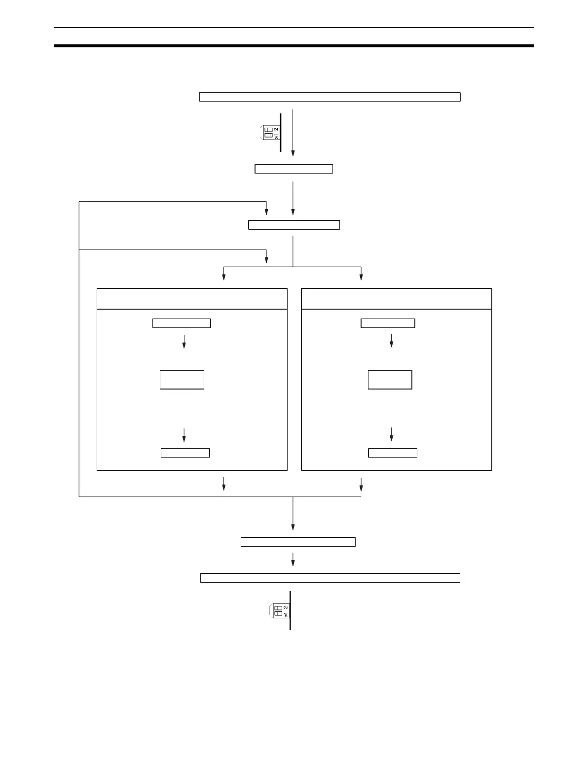
The following diagram shows the flow of operations when using the adjust-
ment mode for adjusting offset and gain.
!Caution Be sure to turn OFF the power to the PLC before changing the setting of the
operation mode switch.
!Caution The power must be cycled or the Unit restarted if the operation mode is set in
DM.
Set the operation mode to adjustment mode.
Turn ON the PLC.
When adjusting another input number
When adjusting the same input number
Set the input number.
Offset adjustment
Offset Bit ON
Set Bit ON
Turn OFF power to the PLC.
Set the operation mode to normal mode.
Gain adjustment
Gain Bit ON
Input adjustment
Set Bit ON
Input adjustment
Set the operation mode switch, or (for version-1 Unit)
set the operation mode in DM Area word m+18 (see
note), to adjustment mode.
(Bit 0 of CIO word
n+1 turns ON.)
Sampling
input
(Add inputs so that
conversion value
becomes 0.)
(Bit 4 of CIO word
n+1 turns ON.)
The ADJ indicator will flash while in adjustment mode.
Start up the PLC in PROGRAM mode.
Write the input number to be adjusted
in the rightmost byte of CIO word n.
(Bit 1 of CIO word
n+1 turns ON.)
Sampling
input
(Add inputs so that
conversion value is
maximized.)
(Bit 4 of CIO word
n+1 turns ON.)
Set the operation mode switch, or set the operation
mode in DM Area word m+18 (see note), to normal
mode.
Note: Set in DM Area word m+19 for CS1W-AD161.
Note: Set in DM Area word m+19 for CS1W-AD161.

 Loading...


