72
Handling Errors and Alarms Section 2-8
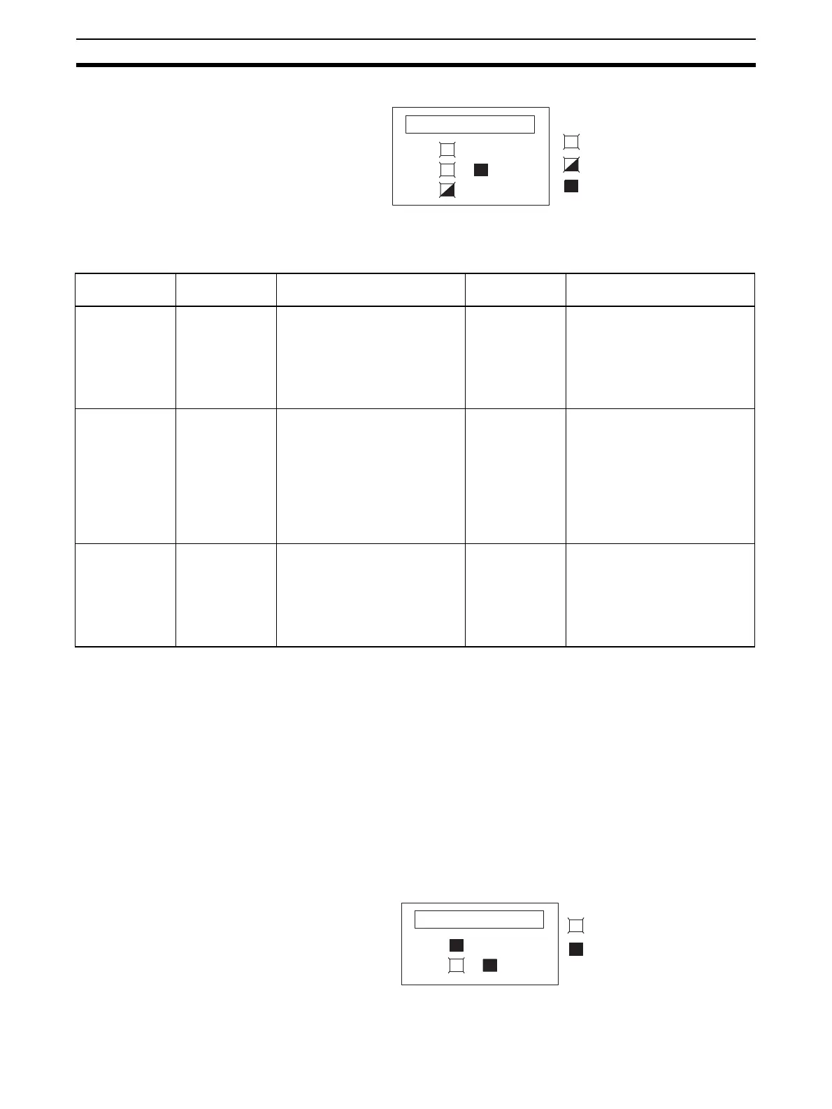
ERC Indicator and RUN Indicator: Lit, ADJ Indicator: Flashing
This alarm will occur in the case of incorrect operation while in the adjustment
mode. In adjustment mode, the Adjustment Mode ON Flag will turn ON in bit
15 of CIO word n+9.
n = CIO 2000 + unit number x 10
Note 1. When a PLC error occurs in the adjustment mode, the Unit will stop oper-
ating. (The input values immediately prior to the error are held.)
2. These alarms are output in CIO word n+9 for CS1W-AD041-V1 and
CS1W-AD081-V1, and in CIO word n+19 for CS1W-AD161.
3. These alarms are output in CIO word n+8 for CS1W-AD041-V1 and
CS1W-AD081-V1, and in CIO word n+18 for CS1W-AD161.
4. The operation mode is set in DM word m+18 for CS1W-AD041-V1 and
CS1W-AD081-V1, and in DM word m+19 for CS1W-AD161.
5. Bit 15 is always ON in adjustment mode. When the PLC is in RUN mode
or MONITOR mode, the ERC indicator will be lit.
ERC Indicator: Lit, RUN Indicator: Not Lit
The ERC indicator will be lit when the initial settings for the Analog Input Unit
are not set correctly. The alarm flags for the following errors will turn ON in
RUN
ERC
ERH
ADJ
: Lit
: Flashing
: Not lit
Word n+9/n+19
(See note 2.)
Alarm flag Error contents Input status Countermeasure
Bit 12 (Adjustment
mode)
Input Value
Adjustment
Range
Exceeded
In adjustment mode, offset or
gain cannot be adjusted
because input value is out of the
permissible range for adjust-
ment.
Conversion data
corresponding
to the input sig-
nal is monitored
in word n+8/
n+18 (see note
3).
If making the adjustment by
means of a connected input
device, first adjust the input
device before adjusting the Ana-
log Input Unit.
Bit 13 (Adjustment
mode)
Input Number
Setting Error
In adjustment mode, adjust-
ment cannot be performed
because the specified input
number is not set for use or
because the wrong input num-
ber is specified.
Holds the values
immediately
prior to the error.
No data is
changed.
• Check whether the word n
input number to be adjusted is
set within the following ranges:
CS1W-AD041-V1: 21 to 24
CS1W-AD801-V1: 21 to 28
CS1W-AD161: 201 to 216
• Check whether the input num-
ber to be adjusted is set for
use by means of the DM set-
ting (DM word m set to 1).
Bit 15 only ON
(See note 5.)
(Adjustment
Mode)
PLC Error
The PLC is in either MONITOR
or RUN mode while the Analog
Input Unit is operating in adjust-
ment mode.
Holds the values
immediately
prior to the error.
No data is
changed.
Set the Unit to normal mode
either by removing the Unit and
setting the DIP switch on the
rear panel or by setting the
mode in DM word m+18 (see
note 4), and then restart the
Unit.
RUN
ERC
ERH
: Lit
: Not lit

 Loading...


