70
Alarm Outputs Section 3-9
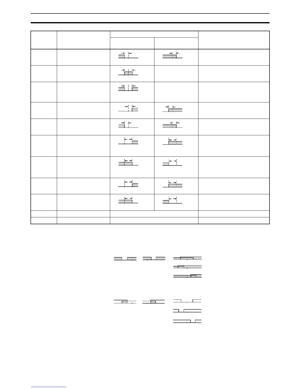
Note (1) With set values 1, 4, and 5, the upper- and lower-limit values can be set
independently for each alarm type, and are expressed as “L” and “H.”
(2) Set value: 1 (Upper- and lower-limit alarm)
(3) Set value: 4 (Lower limit range)
(4) Set value: 5 (Upper- and lower-limit with standby sequence)
• For the lower-limit alarms in cases 1 and 2 above, the alarm is always
OFF if upper- and lower-limit hysteresis overlaps.
• In case 3, the alarm is always OFF.
3 Lower-limit Set the downward deviation in the
set point by setting the alarm value
(X).
4 (See note
1.)
Upper- and lower-limit
range
See note 3. Set the deviation in the set point by
setting the alarm upper limit (H)
and alarm lower limit (L).
5 (See note
1.)
Upper- and lower-limit
with standby sequence
See note 4. A standby sequence is added to
the upper- and lower-limit alarm
(1). (See note 6.)
6 Upper-limit with standby
sequence
A standby sequence is added to
the upper-limit alarm (2). (See note
6.)
7 Lower-limit with standby
sequence
A standby sequence is added to
the lower-limit alarm (3). (See note
6.)
8 Absolute-value upper-
limit
The alarm will turn ON if the pro-
cess value is larger than the alarm
value (X) regardless of the set
point.
9 Absolute-value lower-limit The alarm will turn ON if the pro-
cess value is smaller than the
alarm value (X) regardless of the
set point.
10 Absolute-value upper-
limit with standby
sequence
A standby sequence is added to
the absolute-value upper-limit
alarm (8). (See note 6.)
11 Absolute-value lower-limit
with standby sequence
A standby sequence is added to
the absolute-value lower-limit
alarm (9). (See note 6.)
12 LBA (alarm 1 type only) --- Refer to page 118. (See note 7.)
13 PV change rate alarm --- Refer to page 72. (See note 8.)
Set value Alarm type Alarm output operation Description of function
When alarm value X
is positive
When alarm value X
is negative
X
ON
OFF
SP
X
ON
OFF
SP
LH
ON
OFF
SP
LH
ON
OFF
SP
See note 5.
X
ON
OFF
SP
ON
OFF
SP
X
X
ON
OFF
SP
X
ON
OFF
SP
X
ON
OFF
0
X
ON
OFF
0
ON
OFF
X
0
ON
OFF
X
0
X
ON
OFF
0
X
ON
OFF
0
ON
OFF
X
0
ON
OFF
X
0
LH
H < 0, L > 0
|H| < |L|
SP
LH
H > 0, L < 0
|H| > |L|
SP
LH
H < 0, L < 0
SP
LH
H < 0, L > 0
|H| ≥ |L|
SP
LH
H > 0, L < 0
|H| ≤ |L|
SP
Case 1 Case 2 Case 3 (Always ON)
LH
H < 0, L > 0
|H| < |L|
SP
HL
H > 0, L < 0
|H| > |L|
SP
LH
H < 0, L <