31
Wiring Terminals Section 2-2
Do not connect a different type of terminal block to a Controller. For example,
do not replace a screw terminal block with a screwless clamp terminal block.
The temperature indication accuracy will decrease.
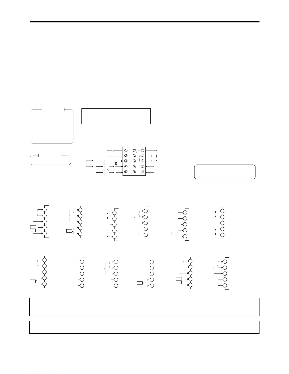
2-2 Wiring Terminals
Confirm the location of the terminals (terminals 1 to 15 for the E5CN, 1 to 30
for the E5AN and E5EN, and terminals 1 to 14 for the E5GN) using the prod-
uct labels and case markings.
2-2-1 Terminal Arrangement
E5CN
Controllers
Option Units
Since the voltage output (control output) is not electrically insulated from the internal wiring, one or other of
the control output terminals must be left unearthed when using an earthed thermocouple thermometer. (Con-
nection makes measurements unreliable due to sneak currents.)
To comply with EMC standards, the length of the cable connecting the analog input or universal TC/Pt input
sensor must be 30 m or less. If the cable is longer than 30 m, the EMC standards will not be satisfied.
Voltage output (for driving SSR)
12 VDC, 21 mA
Control output 2
Relay output
250 VAC, 3 A (resistive load)
Voltage output (for driving SSR)
12 VDC, 21 mA
Current output
0 to 20 mA DC
Load: 600 Ω max.
4 to 20 mA DC
Long-life relay output
250 VAC, 3 A (resistive load)
Control output 1
Auxiliary outputs
(relay outputs)
+
−
A
B
B
TC/Pt
universal input
+
−
Input power
supply
Control output 1
Auxiliary outputs (relay outputs)
250 VAC, 3 A
(resistive load)
• 100 to 240 VAC
• 24 VAC/VDC (no polarity)
DO NOT
USE
+
Analog input
−
+
V
−
DO NOT
USE
DO NOT
USE
Auxiliary output 2
mA
Auxiliary output 1
A heater burnout alarm, heater short alarm,
heater overcurrent alarm, or input error is
sent to the output to which the alarm 1
function is assigned.
The E5@N-@@@T@ is set for a K thermocouple
(input type of 5) by default. If a difference sensor is
used, an input error (s.err) will occur. Check the
setting of the input type parameter.
11
12
13
14
15
CT1
EV1
EV2
E53-CNHBN2
Event inputs
and CT
11
12
13
14
15
E53-CNPBN2
Event Inputs and
External Power Supply
EV1
EV2
+
−
External
power supply
12 VDC,
20 mA
11
12
13
14
15
E53-CNPHN2
External Power
Supply and CT
+
−
External
power supply
12 VDC,
20 mA
DO NOT
USE
CT1
USE
11
12
13
14
15
B(+)
A(−)
RS-485
DO NOT
E53-CNP03N2
Communications (RS-485)
and External Power Supply
+
−
External
power supply
12 VDC,
20 mA
11
12
13
14
15
E53-CNQHN2
Control Output 2
and CT
+
−
Control output 2
11
12
13
14
15
EV1
EV2
E53-CNQBN2
Event Inputs and
Control Output 2
+
−
Control output 2
11
12
13
14
15
CT2
CT1
B(+)
A(−)
RS-485
E53-CNHH03N2
Communications
(RS-485) and CT2
11
12
13
14
15
B(+)
A(−)
RS-485
DO NOT
USE
E53-CNQ03N2
Communications
(RS-485) and
Control Output 2
+
−
Control output 2
11
12
13
14
15
B(+)
A(−)
RS-485
E53-CN03N2
Communications
(RS-485)
11
12
13
14
15
EV1
EV2
E53-CNBN2
Event inputs
11
12
13
14
15
CT2
CT1
E53-CNQHHN2
Control Output 2
and CT2
+
−
Control output 2
11
12
13
14
15
B(+)
A(−)
RS-485
E53-CNH03N2
Communications
(RS-485) and CT
CT1
DO NOT
USE
DO NOT
USE
DO NOT
USE
DO NOT
USE
DO NOT
USE
DO NOT
USE
CT1
DO NOT
USE