32
Wiring Terminals Section 2-2
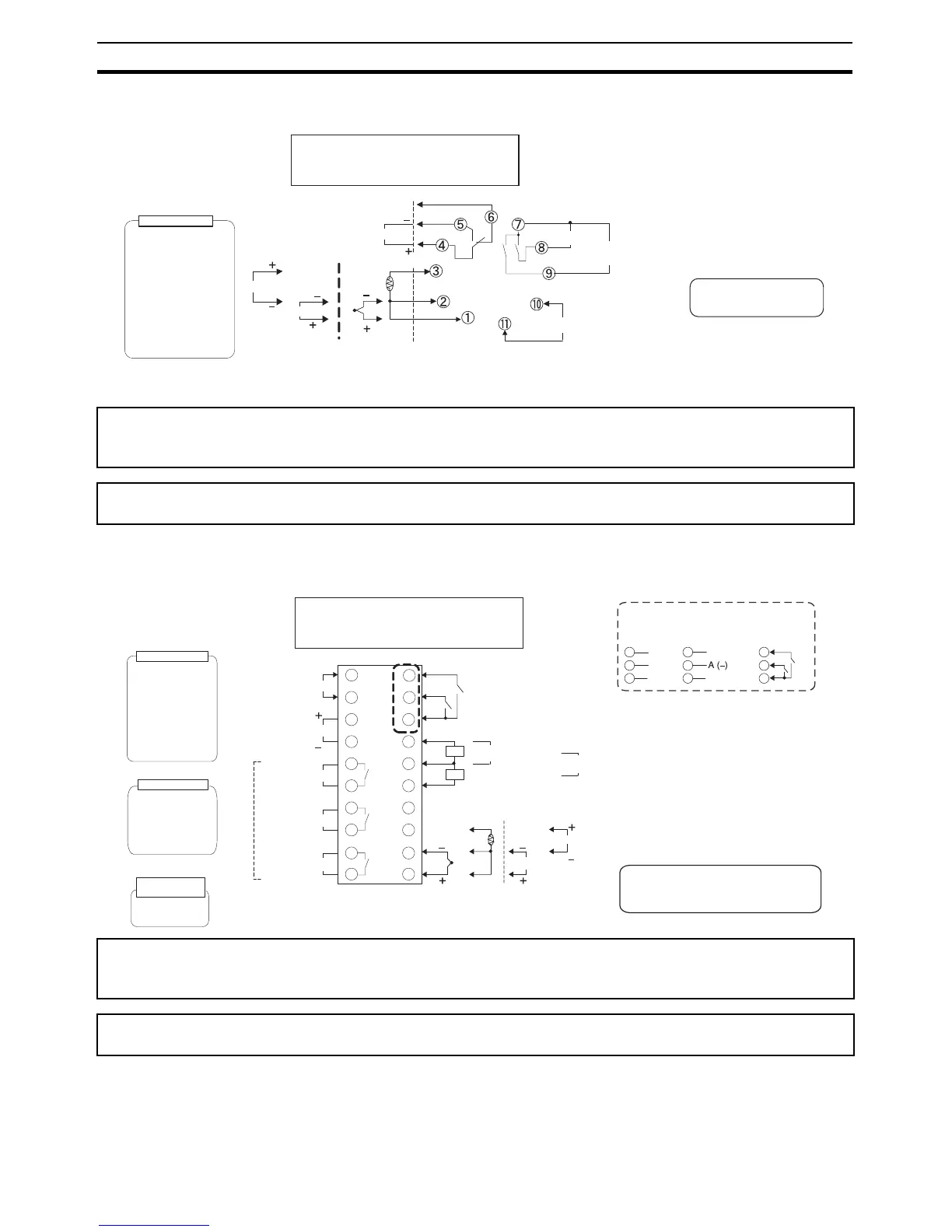
E5CN-U
Note For the Wiring Socket, purchase the P2CF-11 or PG3A-11 separately.
E5AN/EN
Controllers Option Units
Since the voltage output (control output) is not electrically insulated from the internal wiring, one or other of
the control output terminals must be left unearthed when using an earthed thermocouple thermometer. (Con-
nection makes measurements unreliable due to sneak currents.)
To comply with EMC standards, the length of the cable connecting the analog input or universal TC/Pt input
sensor must be 30 m or less. If the cable is longer than 30 m, the EMC standards will not be satisfied.
A
B
B
Auxiliary output
250 VAC, 3 A (resistive load)
Control output 1
TC/Pt
universal input
Input power supply
• 100 to 240 VAC
• 24 VAC/VDC (no polarity)
Auxiliary output 1
(Relay outputs)
DO NOT
USE
Analog input
V
mA
DO NOT
USE
DO NOT
USE
An input error is sent to the
sent to which the alarm 1
function is assigned.
Current output
0 to 20 mA DC
Relay output
(three terminals used)
SPDT, 250 VAC, 3 A
(resistive load)
Voltage output
(for driving SSR)
12 VDC, 21 mA
Load: 600 Ω max.
4 to 20 mA DC
Control output 1
Auxiliary output 2
(Control output (cooling side))
The E5@N-@@@T@ is set for a K thermocouple
(input type of 5) by default. If a difference sensor is
used, an input error (s.err) will occur. Check the
setting of the input type parameter.
Input power supply
Auxiliary output 2
1
2
3
4
5
13
14
15
6
7
8
9
10
16
17
18
19
Control output 1
Analog input
TC/Pt universal input
B
V
mA
Auxiliary output 3
20
CT1
CT2
EV1
EV2
CT1/CT2 Control Output 2
+
-
Control output 2
DO NOT
USE
+
-
External power supply
12 VDC, 20 mA
DO NOT
USE
External Power Supply
DO NOT
USE
B
A
DO NOT
USE
DO NOT
USE
DO NOT
USE
Auxiliary output 1
Event Inputs
11
12
A heater burnout alarm, heater short alarm,
heater overcurrent alarm, or input error is
sent to the output to which the alarm 1
function is assigned.
250 VAC, 3 A
(resistive load)
Relay outputs
Auxiliary output
1, 2, 3
• 100 to 240 VAC
• 24 VAC/VDC (no polarity)
Current output
0 to 20 mA DC
Voltage output
(for driving SSR)
12 VDC, 40 mA
Load: 600 Ω max.
4 to 20 mA DC
Relay output
250 VAC, 5A
(resistive load)
Control output 2
Voltage output
(for driving SSR)
12 VDC, 21 mA
Control output 1
Long-life relay output
250 VAC, 3 A
(resistive load)
Communications
E53-EN03
RS-485
B (+)11
12
DO NOT USE13
E53-EN01
RS-232C
SD11
RD12
SG13
E53-AKB
Event inputs
11
12
13
EV
EV2
CT1/CT2
The E5@N-@@@T@ is set for a K thermocouple
(input type of 5) by default. If a difference sensor is
used, an input error (s.err) will occur. Check the
setting of the input type parameter.