33
Wiring Terminals Section 2-2
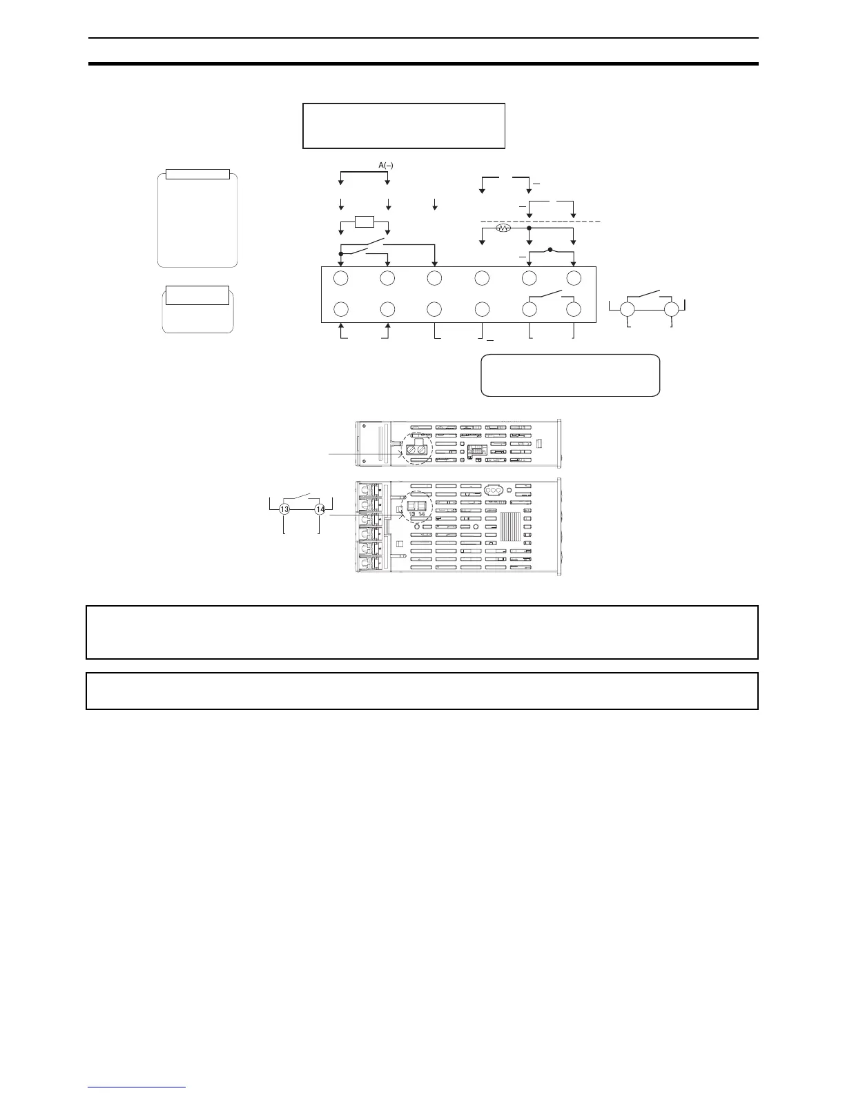
E5GN
2-2-2 Precautions when Wiring
• Separate input leads and power lines in order to prevent external noise.
• Use a shielded, AWG24 to AWG14 (cross-sectional area of 0.205 to
2.081 mm
2
) twisted-pair cable for the E5CN, E5EN, or E5AN. Use a
shielded, AWG24 to AWG18 (cross-sectional area of 0.205 to 0.823 mm
2
)
twisted-pair cable for the E5GN. The stripping length is 5 to 6 mm for the
E5CN, E5AN, or E5EN, and 6 to 8 mm for the E5GN.
• Use crimp terminals when wiring the terminals.
• Use the suitable wiring material and crimp tools for crimp terminals.
• Tighten the terminal screws to a torque of 0.5 N·m for the E5CN-U and
E5GN and to 0.74 to 0.90 N·m for other models. The terminal torque is
0.5 to 0.6 N·m for auxiliary output 2 on the E5GN.
• For the E5CN, E5AN, or E5EN, use the following types of crimp terminals
for M3.5 screws.
Since the voltage output (control output) is not electrically insulated from the internal wiring, one or other of
the control output terminals must be left unearthed when using an earthed thermocouple thermometer. (Con-
nection makes measurements unreliable due to sneak currents.)
To comply with EMC standards, the length of the cable connecting the analog input or universal TC/Pt input
sensor must be 30 m or less. If the cable is longer than 30 m, the EMC standards will not be satisfied.
• 100 to 240 VAC
• 24 VAC/VDC (no polarity)
A heater burnout alarm, heater short alarm,
heater overcurrent alarm, or input error is
sent to the output to which the alarm 1
function is assigned.
Current output
0 to 20 mA DC
Voltage output
(for driving SSR)
12 VDC, 21 mA
Load: 500 Ω max.
4 to 20 mA DC
Relay output
250 VAC, 2 A
(resistive load)
Control output 1
250 VAC, 2 A
(resistive load)
Relay outputs
The E5@N-@@@T@ is set for a K thermocouple
(input type of 5) by default. If a difference sensor is
used, an input error (s.err) will occur. Check the
setting of the input type parameter.
Auxiliary outputs
1 and 2
10 11 12
+
Control
output 1
123 645
789
Input power
supply
Auxiliary
output 1
Auxiliary
output 2
+
Universal TC/Pt input
BBA
+
Analog input
V
DO NOT
USE
DO NOT
USE
EV1
EV2
Event input
CT input
+
mA
DO NOT
USE
CT
SD RD SG
DO NOT
USE
DO NOT
USE
B(+)
1413
RS-485 communications
RS-232C communications
Auxiliary output 2
connection screws
Auxiliary
output 2