208
Initial Setting Level Section 5-7
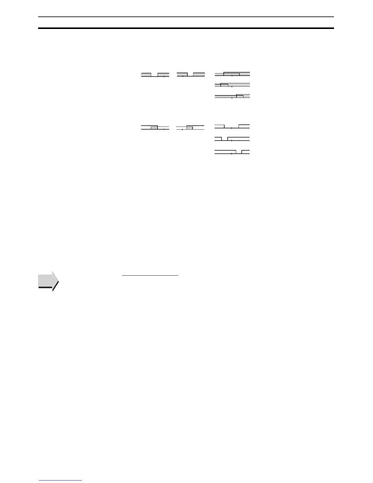
Note (1) With set values 1, 4 and 5, the upper- and lower- limit values can be set
independently for each alarm type, and are expressed as “L” and “H.”
(2) Set value: 1 (Upper- and lower-limit alarm)
(3) Set value: 4 (Lower limit range)
(4) Set value: 5 (Upper- and lower-limit with standby sequence)
• For the lower-limit alarms in cases 1 and 2 above, the alarm is normal-
ly OFF if upper- and lower-limit hysteresis overlaps.
• In case 3, the alarm is always OFF.
(5) Set value: 5 (The alarm is always OFF if upper- and lower-limit alarm hys-
teresis with standby sequence overlaps.)
(6) Refer to 4-2-1 Standby Sequence for information on the operation of the
standby sequence.
(7) Refer to 4-12-1 Loop Burnout Alarm (LBA)
(8) Refer to PV Change Rate Alarm on page 72.
• Set the alarm type independently for each alarm in the Alarm 1 to 3 Type
parameters in the initial setting level. The default is 2 (Upper-limit alarm).
■ Related Parameters
Alarm value 1: Page 172, Alarm value upper limit 1, Alarm value lower limit 1:
Page 174 (operation level)
Standby sequence reset: Page 221, Auxiliary output 1 open in alarm: Page
222, Alarm 1 latch: Page 227 (advanced function setting level), Alarm 1 hys-
teresis: Page 209 (initial setting level)
LH
H < 0, L > 0
|H| < |L|
SP
LH
H > 0, L < 0
|H| > |L|
SP
LH
H < 0, L < 0
SP
LH
H < 0, L > 0
|H| ≥ |L|
SP
LH
H > 0, L < 0
|H| ≤ |L|
SP
Case 3 (Always ON)Case 2Case 1
LH
H < 0, L > 0
|H| < |L|
SP
HL
H > 0, L < 0
|H| > |L|
SP
LH
H < 0, L < 0
SP
L
L
H
H
H < 0, L > 0
|H| ≥ |L|
SP
SP
H > 0, L < 0
|H| ≤ |L|
Case 3 (Always OFF)
Case 2Case 1
See
See