6 Parameters
6 - 8
E5@C-T Digital Temperature Controllers User’s Manual (H185)
Process Value/Set Point 1 PV/SP No. 1 Display Selection must not be set to 0.
Process Value/Set Point 2 PV/SP No. 2 Display Selection must not be set to 0.
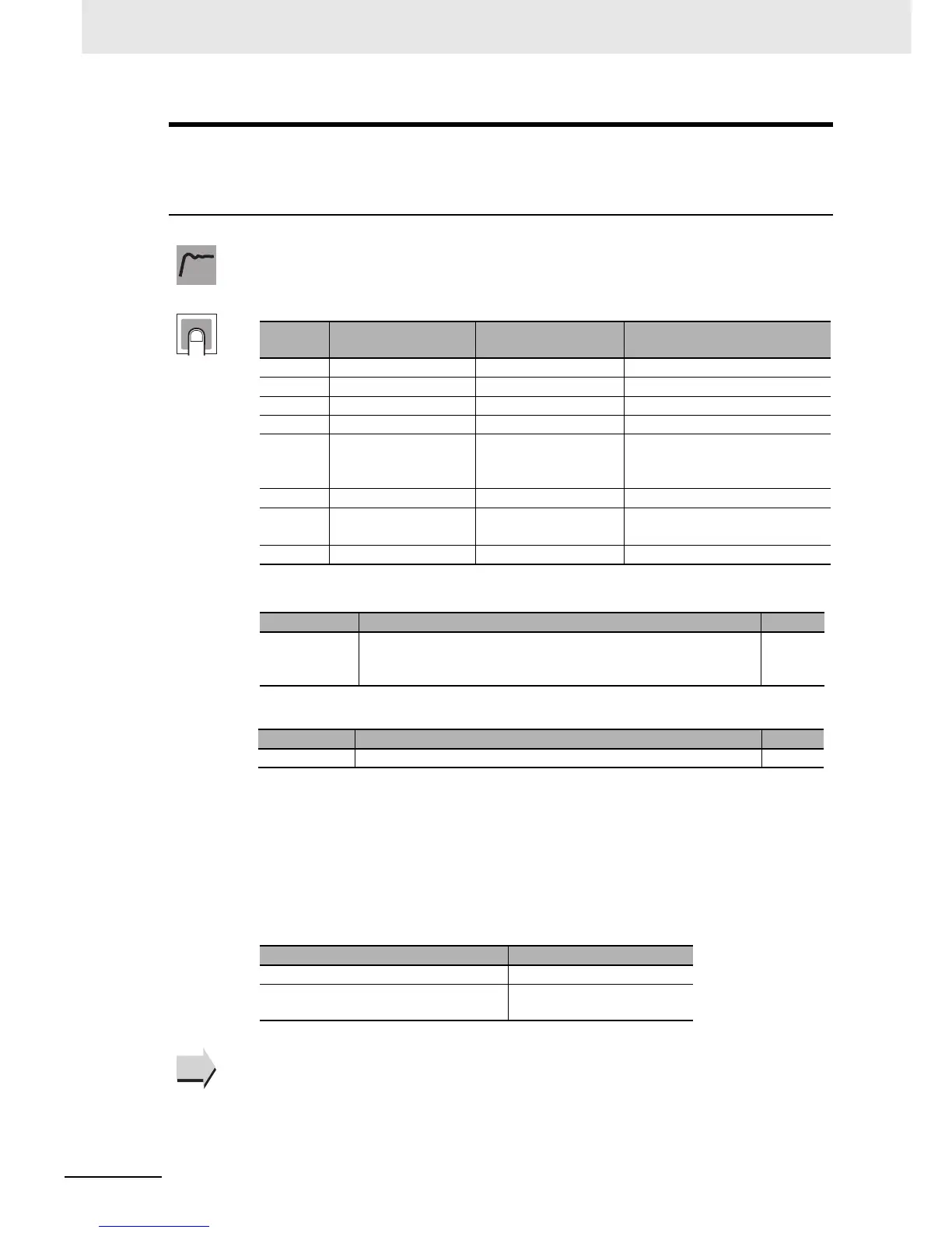
The following table shows the contents of the No. 1, 2, and 3 displays, according to the set-
ting of the PV/SP Display Screen Selection parameter.
* The SP can be set in Fixed SP Mode (FSP). In Program SP Mode (PSP), the SP is displayed for
reference only.
During temperature input, the decimal point position depends on the currently selected sen-
sor, and during analog input it depends on the Decimal Point parameter setting.
PV/SP Display Selections
z Related Parameters
PV/SP Display Selection (Advanced Function Setting Level): Page 6-107
Function
Setting
Set value No. 1 display No. 2 display
No. 3 display
(E5EC-T/E5AC-T only)
0 Nothing is displayed. Nothing is displayed. Nothing is displayed.
1 Process value Set point Nothing is displayed.
2 Process value Nothing is displayed. Nothing is displayed.
3 Set point SP (character display) Nothing is displayed.
4 Process value Set point MV monitor (heating) (valve
opening for Position-proportional
Models)
5 Process value Set point MV monitor (cooling)
6 Process value Set point Program No. monitor/Segment
No. monitor
7 Process value Set point Remaining segment time
Monitor range Unit
Process value Temperature input: The specified range for the specified sensor.
Analog input: Scaling lower limit −5% FS to Scaling upper limit +5%
FS
EU
Setting range Unit
Set point SP lower limit to SP upper limit* EU
Parameter Default
PV/SP No. 1 Display Selection 6
PV/SP No. 2 Display Selection E5CC-T: 0
E5EC-T/E5AC-T: 7
See
See