6 Programless Communications
6 - 22
E5@C Digital Temperature Controllers Communications Manual (H175)
6-4 Connecting to CP-series PLCs
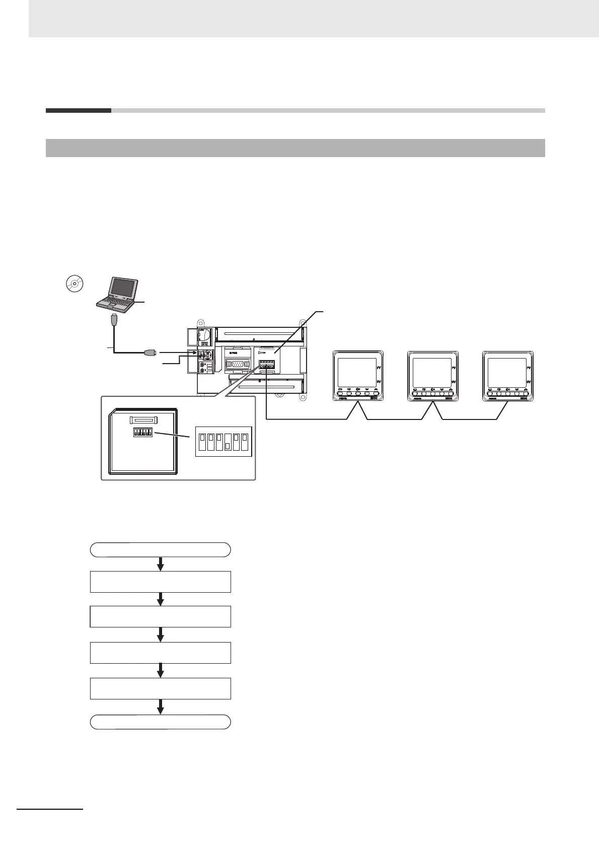
The following configuration is used as an example in giving the setup and application procedures for
programless communications.
• All of the E5CC Controllers must be the same model. (Copying parameter settings is not possible if
the models are different.)
• D0000 to D0089 are used in the PLC memory. The default E5CC parameter allocations are used.
• A commercially available USB2.0, A/B cable is used.
Note: Refer to the CX-Programmer Operation Manual (Cat. No. W446) for information on installing the
CX-Programmer and USB driver.
The application procedure is given below.
6-4-1 Configuration and Procedure
CX-Programmer
Support Software
USB port
Peripheral (USB) port
25
0
C
25
0
C
25
0
C
RS-485
RS-422A/RS-485 Option Board
CP1W-CIF11
E5CC
No.0
E5CC
No.1
E5CC
No.2
CP1E CPU Unit
CP1E-N30D@-@
Commercially
available USB
cable
IBM PC/AT or compatible
Back of CP1W-CIF11
DIP switch
for operation settings
1
2
3
4
5
6
O
N
START
Set the switches and wire the system.
Set the switches on the CP1W-CIF11 and wire it to the E5CC Controllers.
Set up the E5@C Controllers. Set up programless communications in the E5CC Controllers.
Check operation. Use the CX-Programmer to confirm that programless communications are operating.
Set up the PLC. Use the CX-Programmer to set up communications on the CP1E to enable
communicating with the E5CC Controllers.
END