6 - 9
6 Programless Communications
E5@C Digital Temperature Controllers Communications Manual (H175)
6-2 E5C Setup
6
6-2-5 Areas and First Address of Linked Data
Communications Setting Level
Display condition: The Protocol Setting parameter must be set to fins, mcp4, or fxp4, or the Protocol
Setting parameter must be set to cmp and the Communications Unit No. parameter must be set to 0
(master).
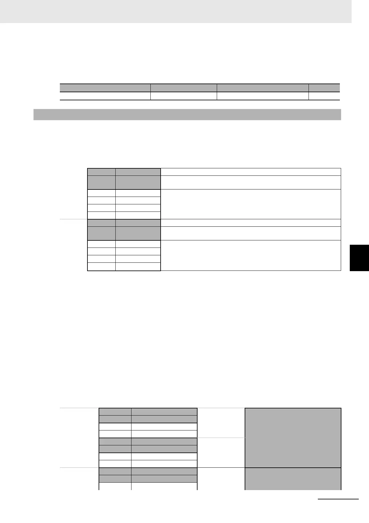
Two areas are used in PLC memory by the E5@C, an upload area and a download area. The upload
area is used to monitor the process value, status, and other information from the E5@C. The download
area is used to write the set point, alarm values, and other values to the E5@C.
The Response Flag, Communications Status, Request Flag, and Operation Command Code all have
special functions that cannot be changed. Refer to the following sections for application methods.
Request Flag: 6-3-1 Controlling Programless Communications with the Request Flag
Response Flag: 6-3-2 Response Flag
Operation Command Code: 6-3-4 Operation Command Codes
Communications Status: 6-3-5 Confirming Operation of Programless Communications
The portion of PLC memory to use is set with the Area, First Address Upper Word, and First Address
Lower Word parameters.
Note: If more than one E5@C Controller is connected to the same communications line, set the starting address to
the same value for all of them. The E5@C Controller with communications unit number 0 will use the words
that start from the specified starting address, the E5@C Controller with unit number 1 will use the words that
start from the specified starting address plus 30 words, and the E5@C Controller with unit number 2 will use
the words that start from the specified starting address plus 60 words
Parameter name Displayed characters Setting range Default
Highest Communications Unit No. maxu 0 to 99 0
6-2-5 Areas and First Address of Linked Data
Address Data in PLC
memory
Upload
Area
XXXX Response Flag This flag indicates the completion of processing for the Request Flag.
+1 Communications
Status
The status that is given at this address is used in the PLC to check the operation
of programless communications.
+2 Monitor Value 1 Information from the E5@C, such as the PV or status, is set at these addresses.
The parameters that are actually used are set in the upload settings.
+3 Monitor Value 2
· · ·
+14 Monitor Value 13
Download
Area
+15 Request Flag This flag is used to control programless communications.
+16 Operation
Command Code
The operation command that corresponds to the code is sent.
+17 Set Value 1 The set values at these addresses are written to the E5@C, such as to the set
point or alarm values. The parameters that are actually used are set in the
download settings.
+18 Set Value 2
· · ·
+29 Set Value 13
Address Data in PLC memory E5@C
Each E5@C
Controller is
allocated 30
words.
XXXX Response Flag
←
Communications Unit Number 0
+1 Communications Status
+2 Monitor Value 1
· · ·
+15 Request Flag
→
+16 Operation Command Code
+17 Set Value 1
· · ·
+30 Response Flag
←
No.1+31 Communications Status
· · · · · ·