5 Communications Data for Modbus
5 - 2
E5@C Digital Temperature Controllers Communications Manual (H175)
5-1 Variable Area (Setting Range) List
• Four-byte Mode
One element uses 4 bytes of data (H'00000000 to H'FFFFFFFF), so specify two-element units.
Reading and writing in 4-byte units is executed by specifying an even address and specifying the
number of elements in multiples of 2.
• Two-byte Mode
One element uses 2 bytes of data (H'0000 to H'FFFF), so specify one-element units. Reading and
writing in 2-byte data units is executed by specifying 1-element units.
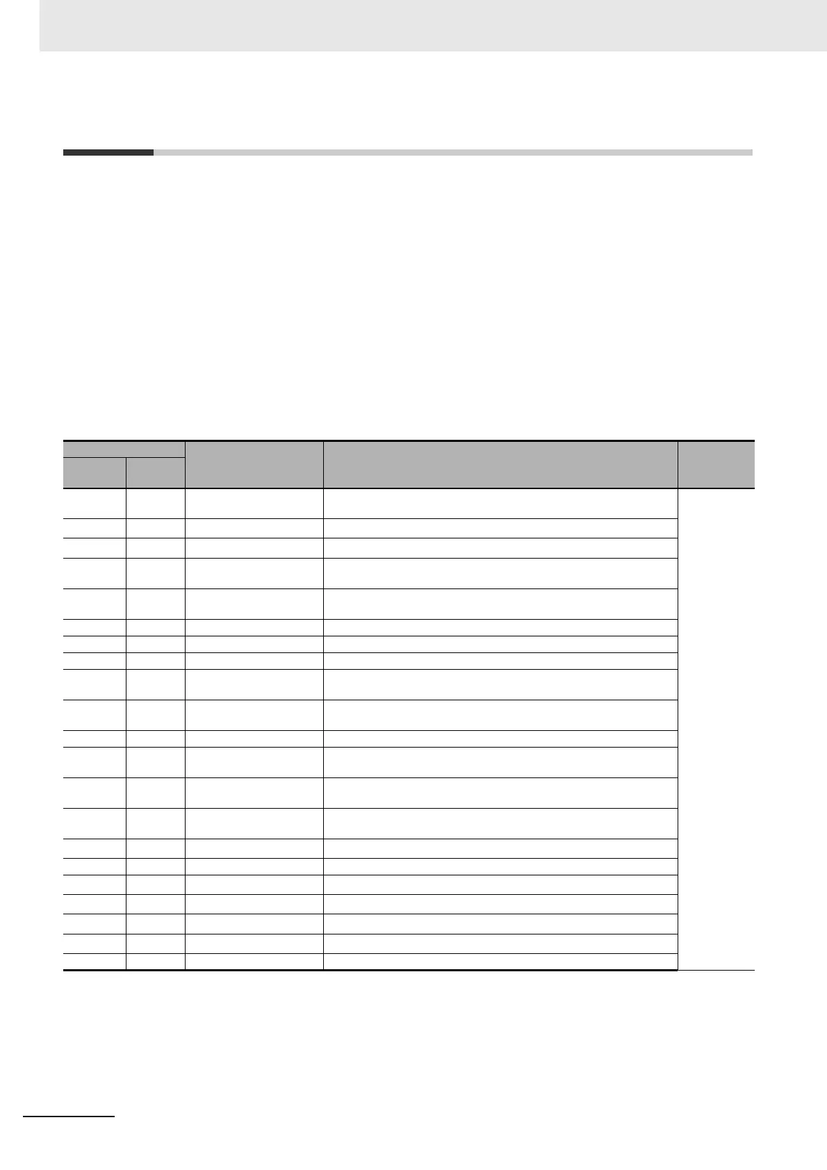
The following table lists the variable area. Items expressed in hexadecimal in the "Setting (monitor)
value" column are the setting range in the Modbus specifications. Values in parentheses "()" are the
actual setting range.
When there is a section reference for a setting item, refer to that reference for details.
Address
Parameter name Setting (monitor) value Level
Four-byte
mode
Two-byte
mode
0000 2000 PV Temperature: Use the specified range for each sensor.
Analog: Scaling lower limit − 5% FS to Scaling upper limit + 5% FS
Operation
0002 2001
Status
*1*2
Refer to 5-2 Status for details.
0004 2002
Internal Set Point
*1
SP lower limit to SP upper limit
0006 2003 Heater Current 1 Value
Monitor
H'00000000 to H'00000226 (0.0 to 55.0)
0008 2004 MV Monitor (Heating) Standard: H'FFFFFFCE to H'0000041A (−5.0 to 105.0)
Heating and cooling: H'00000000 to H'0000041A (0.0 to 105.0)
000A 2005 MV Monitor (Cooling) H'00000000 to H'0000041A (0.0 to 105.0)
0106 2103 Set Point SP lower limit to SP upper limit
0108 2104 Alarm Value 1 H'FFFFF831 to H'0000270F (−1999 to 9999)
010A 2105 Alarm Value Upper Limit
1
H'FFFFF831 to H'0000270F (−1999 to 9999)
010C 2106 Alarm Value Lower Limit
1
H'FFFFF831 to H'0000270F (−1999 to 9999)
010E 2107 Alarm Value 2 H'FFFFF831 to H'0000270F (−1999 to 9999)
0110 2108 Alarm Value Upper Limit
2
H'FFFFF831 to H'0000270F (−1999 to 9999)
0112 2109 Alarm Value Lower Limit
2
H'FFFFF831 to H'0000270F (−1999 to 9999)
0404 2402 PV Temperature: Use the specified range for each sensor.
Analog: Scaling lower limit − 5% FS to Scaling upper limit + 5% FS
0406 2403
Internal Set Point
*1
SP lower limit to SP upper limit
0408 2404 Multi-SP No. Monitor H'00000000 to H'00000007 (0 to 7)
040C 2406
Status
*1*2
Refer to 5-2 Status for details.
040E 2407
Status
*3
Refer to 5-2 Status for details.
0410 2408
Status 2
*1*2
Refer to 5-2 Status for details.
0412 2409
Status 2
*1*3
Refer to 5-2 Status for details.
0420 2410 Decimal Point Monitor H'00000000 to H'00000003 (0 to 3)
*1 Not displayed on the Controller display.
*2 In 2-byte mode, the rightmost 16 bits are read.
*3 In 2-byte mode, the leftmost 16 bits are read.