EasyManuals Logo

Omron E5EC Communications Manual

Omron E5EC
224 pages
To Next Page IconTo Next Page
To Previous Page IconTo Previous Page
Page #28 background imageLoading...
Page #28 background image
1 Communications Methods
1 - 6
E5@C Digital Temperature Controllers Communications Manual (H175)
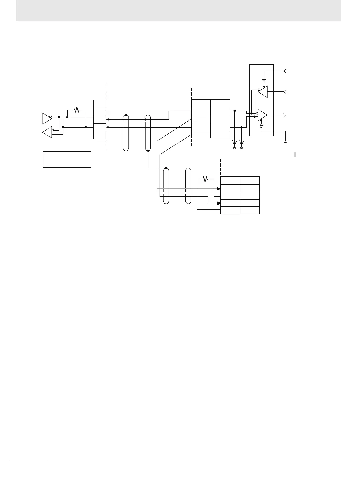
E5@C-B (Models with Push-In Plus Terminal Blocks)
Abbreviation
Host
RS-485
AbbreviationPin
20
19
18
17
E5@C-B
RS-485
Shield
Terminating
resistance
120
Ω
(1/2 W)
6.8 V
TX
RX
Use 120
Ω (1/2 W)
terminating resistance.
Communications transceiver
Shield
E5@C-B
End node
RS-485
AbbreviationPin
20
19
18
17
A < B: “1” Mark
A > B: “0” Space
* Terminals 17 and 18 and terminals 19 and 20 are
connected internally. You can connect to either terminal.
FG
+
SG
A ()
A ()
B (+)
B (+)
A ()
A ()
B (+)
B (+)
Specify both ends of the transmission path
including the host as the end nodes (that
is, connect terminating resistance to both
ends). Use a terminating resistance of at
least 54
Ω.

Table of Contents

Other manuals for Omron E5EC

Questions and Answers:

Question and Answer IconNeed help?

Do you have a question about the Omron E5EC and is the answer not in the manual?

Omron E5EC Specifications

General IconGeneral
Mounting TypePanel Mount
Display Resolution0.1°C or 1°C
Control MethodON/OFF
Input TypeThermocouple, RTD, Analog voltage
Supply Voltage100 to 240 VAC
Output TypeRelay, Voltage, Current
Size48 x 96 mm
Control OutputRelay, Voltage, Current
Alarm OutputRelay
CommunicationRS-485
Ambient Operating Temperature-10 to 55°C
Ambient Operating Humidity25 to 85% RH
Protection RatingIP20

Related product manuals