7
Overview of System Startup Procedure Section 2-1
• Connecting the Power Cable
Align the polarizing key, insert the connector of the power cable into the
power connector on the Slave Unit, and then tighten the lock nut. The
Slave Unit requires a 24-VDC power supply.
Note Do not turn ON the power to the Slave Unit yet.
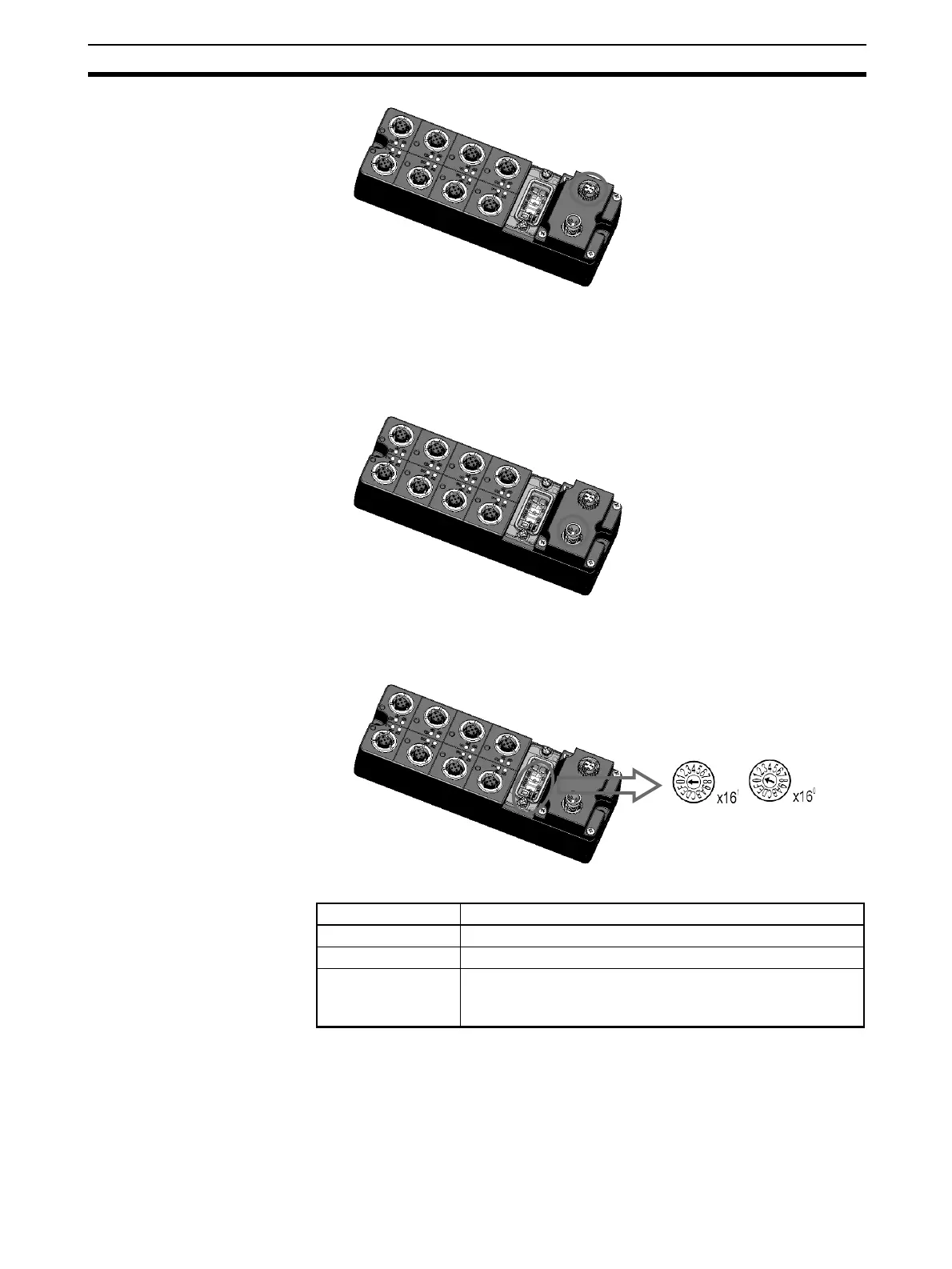
• Rotary Switches
The relationship between the rotary switches on the Slave Unit and the IP
address is shown below.
• Slave Default Settings
The default settings are as follows:
• Rotary switches: 00
• IP address: BOOTP
Rotary switches IP address
00 BOOTP/software setting
01 to FE 192.168.250.n (n = 01 to FE hex: Rotary switch setting)
FF Restores the default setting.
(To restore the default setting, set the switches to FF hex,
cycle the power supply, and then set the switches to 00 hex.)
 Loading...


