79
Troubleshooting Section 7-2
7-2-2 Troubleshooting by Slave Unit Type
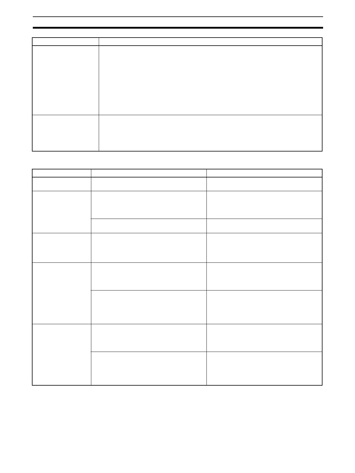
NS indicator remains not
lit and status does not
change.
The Slave Unit is not participating in the network.
• Check that all Slave Unit connectors are connected correctly.
• Check that the Master Unit is operating correctly. If using an OMRON Master Unit, check the
Master Unit mode and the Slave Unit node addresses.
• If using a Master from another manufacturer, refer to the user's manual for that Master.
• Check that the communications cable is wired correctly.
• Check that the power supply cable and power supply are wired correctly and that the set-
tings are correct.
• Check connector wiring to make sure that the communications cable and power supply
cables are not disconnected.
NS indicator remains lit
green and status does
not change.
Check the following items and take corrective measures based on the Master Unit indicator
display.
• Check that the Master Unit is operating correctly. Refer to the manual for the Master Unit.
• Check that the tag data links are set correctly.
• Reset the tag data links.
Model Problem Cause
All Slave Units The MS and NS indicators do not light green. Refer to 7-2-1 Indicators Are Lit or Flashing
Red.
Slave Units with out-
puts
Cannot hold outputs when communications
errors occur.
The Unit is set to clear outputs for communica-
tions errors.
Change the setting to hold outputs for commu-
nications errors.
Cannot clear outputs when communications
errors occur.
Change the setting to clear outputs for commu-
nications errors.
Slave Units with
inputs
There is a delay with the ON and OFF timing for
input values.
An input filter may be set.
Set the input filter value to No Display.
Alternatively, change the input filter to an
appropriate value.
Slave Units with
Unconnected Line
Detection Function
The Unconnected Line Detection Status Flag
turned ON for an unused input.
Unconnected line detection is enabled for an
unused input.
Disable unconnected line detection for that
input.
The Unconnected Line Detection Status Flag
turned ON even though the sensor power sup-
ply was connected.
Current consumption is low.
(Output current: 3 mA max.)
Disable unconnected line detection for that
input (so that the unconnected line detection
function does not operate.)
Slaves with Discon-
nected Line Detec-
tion
The Disconnected Line Detection Status Flag
turned ON for an unused output.
Disconnected line detection is enabled for an
unused output.
Disable disconnected line detection for that out-
put.
The Disconnected Line Detection Status Flag
turned ON even though the external load was
connected.
Current consumption is low.
(Output current: 3 mA max.)
Disable disconnected line detection for that out-
put (so that the disconnected line detection
function does not operate.)
Problem Cause and possible corrections
 Loading...


