61
Environment-resistive Slave Units Section 5-2
5-2 Environment-resistive Slave Units
The Environment-resistive Slave Units are designed to be easily connected
with M12 connectors that lock by turning them 1/8 of a turn for less wiring.
5-2-1 Mounting in Control Panels
Use screws to mount a Waterproof Terminal in a control panel. These Termi-
nals cannot be mounted on a DIN Track.
Drill the mounting holes in the control panel according to the dimensions
shown in the dimensions diagrams and secure the Terminal with M5 screws.
The appropriate tightening torque is 1.47 to 1.96 N⋅m.
Installation Direction The Terminal can be mounted in any direction. Any one of the following 6
directions is acceptable.
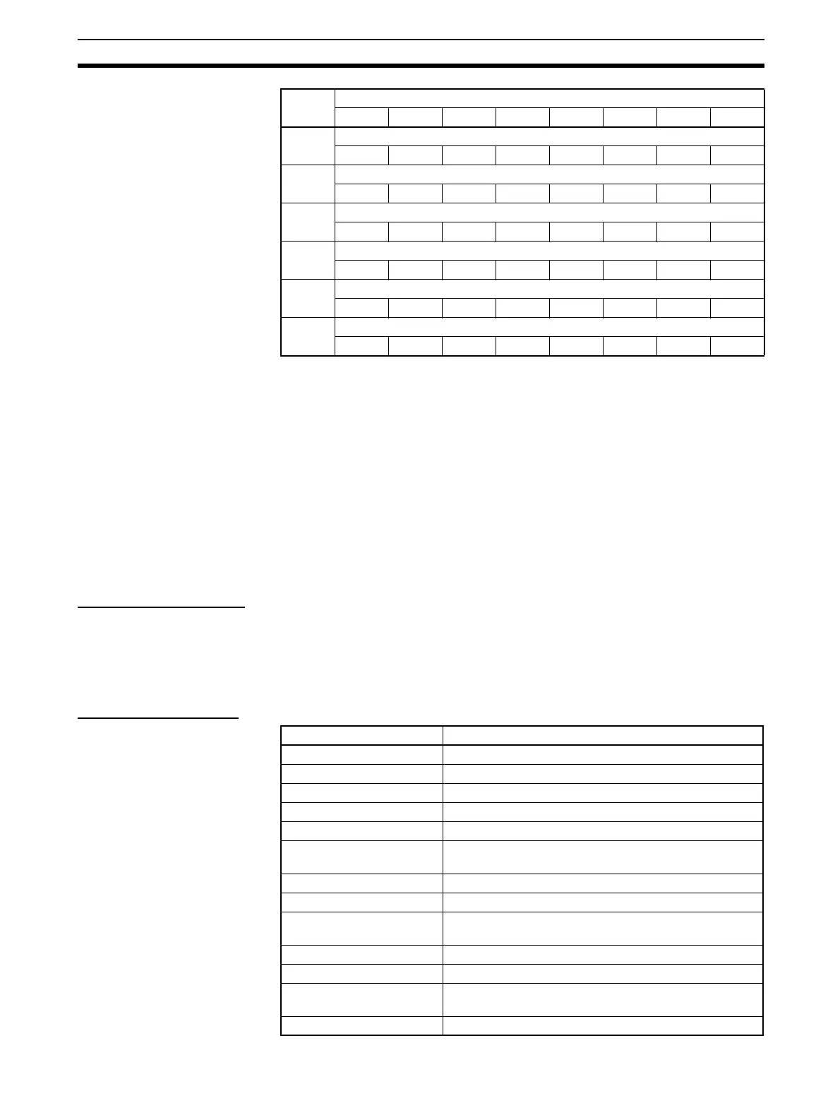
5-2-2 Environment-resistive Terminals with 16 Transistor Inputs (IP67)
ERT1-HD16CH-1
Input Specifications
2 Power or Load Short-circuit Detection Flags for Terminal Block 2
07 06 05 04 03 02 01 00
3 Power or Load Short-circuit Detection Flags for Terminal Block 2
15 14 13 12 11 10 09 08
4 Disconnection Flags for Terminal Block 1
07 06 05 04 03 02 01 00
5 Disconnection Flags for Terminal Block 1
15 14 13 12 11 10 09 08
6 Disconnection Flags for Terminal Block 2
07 06 05 04 03 02 01 00
7 Disconnection Flags for Terminal Block 2
15 14 13 12 11 10 09 08
Byte
offset
Data
Bit 07 06 05 04 03 02 01 00
Item Specifications
Input points 16 points
Internal I/O common PNP
ON voltage 15 V DC min. (between each input terminal and 0 V)
OFF voltage 5 V DC max. (between each input terminal and 0 V)
OFF current 1.0 mA max.
Input current 6.0 mA max. at 24 V DC
3.0 mA max. at 17 V DC
ON delay time 1.5 ms max.
OFF delay time 1.5 ms max.
Number of circuits per
common
16 inputs/common
Isolation method Photocoupler
Input indicators LEDs (yellow)
Power supply short-circuit
protection
Operates at 50 mA/point min.
Disconnection detection Operates at 0.2 mA/point max.
 Loading...


