22
Overview of System Startup Procedure Section 2-1
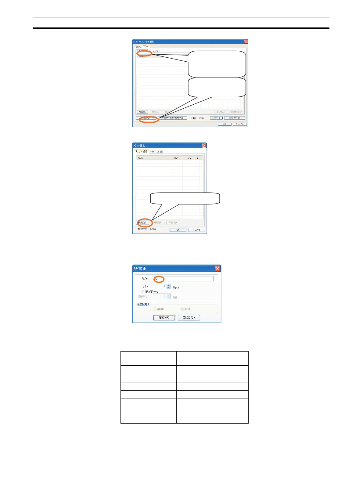
The Edit Tags Dialog Box will be displayed. Click the New Button.
Set the tag name and size. Set the size in increments of 2 bytes. The input
size must be the same as the output size of the target device. Click the
Register Button to register the tag.
The tag name depends on the physical address, as shown below. *Ad-
dresses that do not appear in the following table cannot be specified. Also,
the number of EM banks varies with the CPU Unit of the PLC.
The Edit Tag Dialog Box shown below will be displayed. When you are fin-
ished registering tags, click the Close Button.
Physical address Address (text to input in
Name Field)
CIO Area 0000 to 6143
Holding Area H000 to H511
Work Area W000 to W511
DM Area D00000 to D32767
EM Area Bank 0 E0_00000 to E0_32767
to to
Bank 24 E18_00000 to E18_32767
Make sure that the In-
Consume Tab.
Click the Edit Tags
Button.
Click the New Button.
 Loading...


