EasyManuals Logo

Omron fh series Robot Connection Guide

Omron fh series
54 pages
To Next Page IconTo Next Page
To Previous Page IconTo Previous Page
Page #39 background imageLoading...
Page #39 background image
37
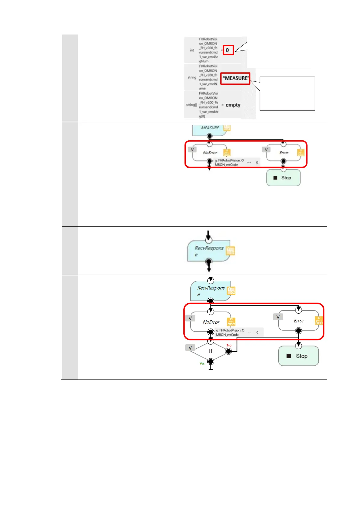
Make sure that [cmdName] is
[MEASURE].
By executing the [MEASURE]
node, measurement command
is sent to the Vision Sensor.
3
Check for the error in the
[MEASURE] node.
The error is stored in the
global variable
[g_FHRobotVision_OMRON_err
Code].
If the error code is 0 (zero),
proceed to the next node.
4
The [RecvResponse] node
receives the response to the
measurement command.
5
Check for the error in the
[RecvResponse] node.
The error is stored in the
global variable
[g_FHRobotVision_OMRON_err
Code].
If the error code is 0 (zero),
proceed to the next node.
Non-procedure
Communication
Commad
fhrunrecvres Component
Number of command
arguments

Other manuals for Omron fh series

Questions and Answers:

Question and Answer IconNeed help?

Do you have a question about the Omron fh series and is the answer not in the manual?

Omron fh series Specifications

General IconGeneral
TypeMachine Vision System
SeriesFH Series
Power Supply24 VDC
Storage Temperature-20 to 60°C
Humidity35 to 85% RH (non-condensing)
Image SensorCMOS
Processing SpeedHigh-speed processing
ConnectivityEthernet
I/ODigital I/O
Operating SystemEmbedded OS
I/O PortsEthernet, USB

Related product manuals