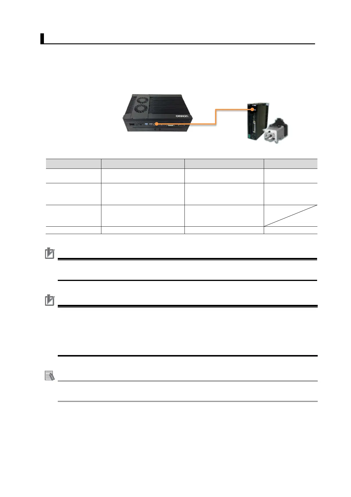
5.2. Device Configuration
The hardware components to reproduce the connection procedures in this document are as
follows:
Manufacturer Name Model Version
OMRON
Programmable Multi-Axis
Controller
Model NY51□-A□□□
OMRON
with Built-in EtherCAT
Model R88D-KN01L-ECT Ver.2.1
OMRON
industrial Ethernet
Model
XS5W-T421-M-K
Precautions for Correct Use
Prepare the ESI file described in this section in advance. Contact your OMRON
representative for information on how to procure the ESI file.
Precautions for Correct Use
Do not share the connection line of EtherCAT communications with other Ethernet networks.
Do not use devices for Ethernet such as a switching hub.
Use the Ethernet cable (double shielding with aluminum tape and braiding) of Category 5 or
higher, and use the shielded connector of Category 5 or higher.
Connect the cable shield to the connector hood at both ends of the cable.
Additional Information
This document describes model NY51□-A□□□ as an example. The same procedures can
apply to model CK3E-□□□□/ CK3M-CPU1□1.
Model NY51□-A□□□
Model R88D-KN-ECT-L
communications

 Loading...


