5 EtherCAT Communications
5 - 16
GX-series EtherCAT Slave Unit User’s Manual
Saving node address settings
If the node address switches are set to 00, the software setting is enabled and the node address that
is set on the Sysmac Studio is used.
To use the software setting, execute the Write Slave Node Address menu command on the Edit
Network Configuration Tab Page for EtherCAT. The software setting will be saved in non-volatile
memory in the Slave Unit.
• Software setting
The software setting that is set in the SII (slave information interface) in non-volatile memory in the
Slave Unit is used as the node address.
• Node address switch setting
The value that is set on the node address switches on the Slave Unit is used as the node address.
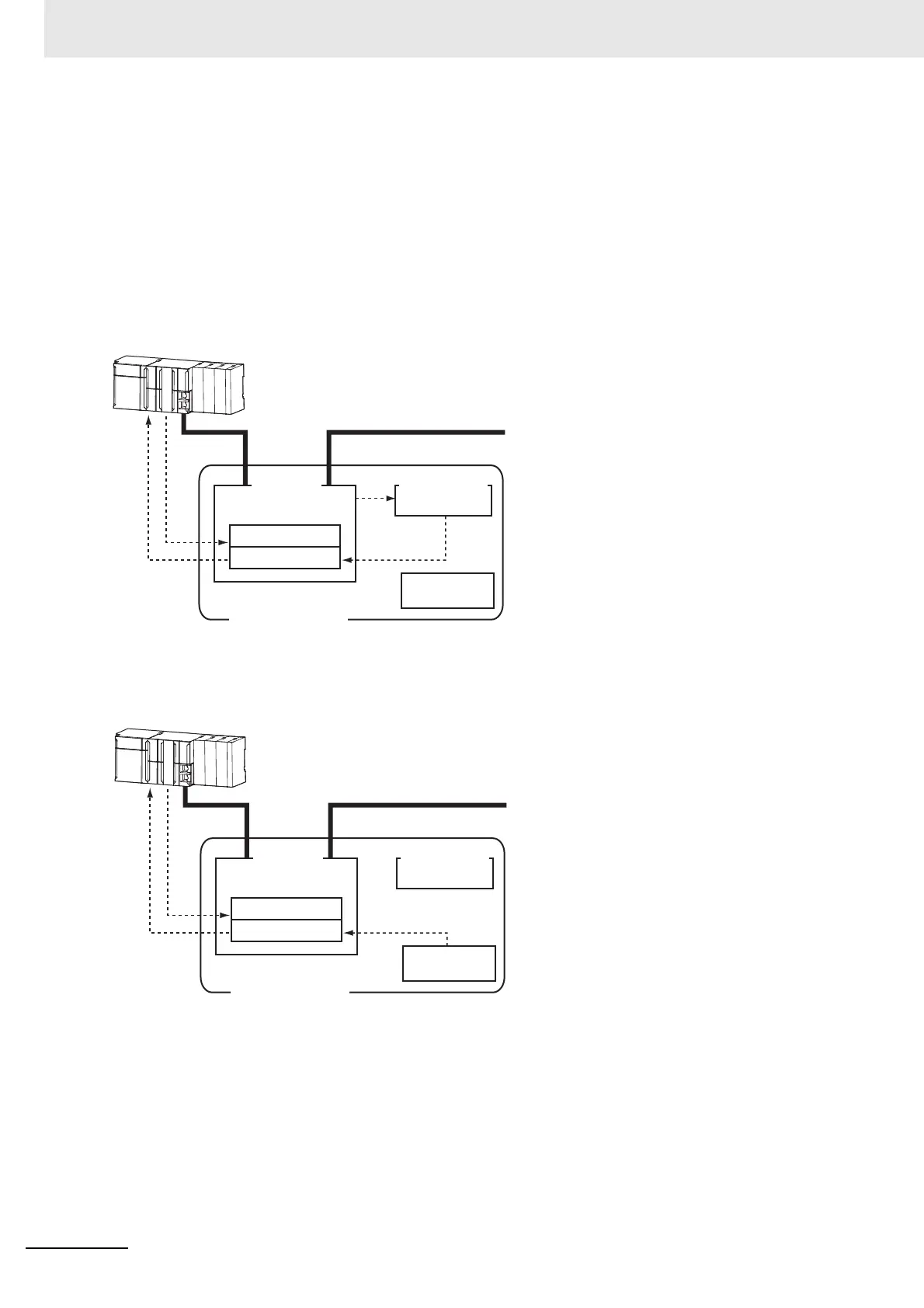
(1)
(2)
(3)
(4) (5)
Node address
switches
EtherCAT Slave Unit
Register: 0010 hex
Register: 0012 hex
EtherCAT
slave controller
EtherCAT Master Unit
Non-volatile memory
SII
(1) When the power supply is OFF, set the node
address switches to 00.
(2) From the master, write the node address to the
SII in the Slave Unit.
(3) When the power supply to the Slave Unit is
turned ON, the software writes the node
address setting to register address 0012 hex.
(4) The EtherCAT Master Unit reads the setting in
register address 0012 hex.
(5) The EtherCAT Master Unit writes the value of
address 0012 hex to address 0010 hex.
(1)
(2)
(3) (4)
Node address
switches
EtherCAT Slave Unit
Register: 0010 hex
Register: 0012 hex
EtherCAT
slave controller
EtherCAT Master Unit
Non-volatile memory
SII
(1) When the power supply is OFF, set the node
address switches.
(2) When the power supply to the Slave Unit is
turned ON, the value that is set on the node
address switches is saved in register address
0012 hex.
(3) The EtherCAT Master Unit reads the setting in
register address 0012 hex.
(4) The EtherCAT Master Unit writes the value of
address 0012 hex to address 0010 hex.
 Loading...


