4 Screen Creation
4-22
NB-series Programmable Terminals Startup Guide Manual(V109)
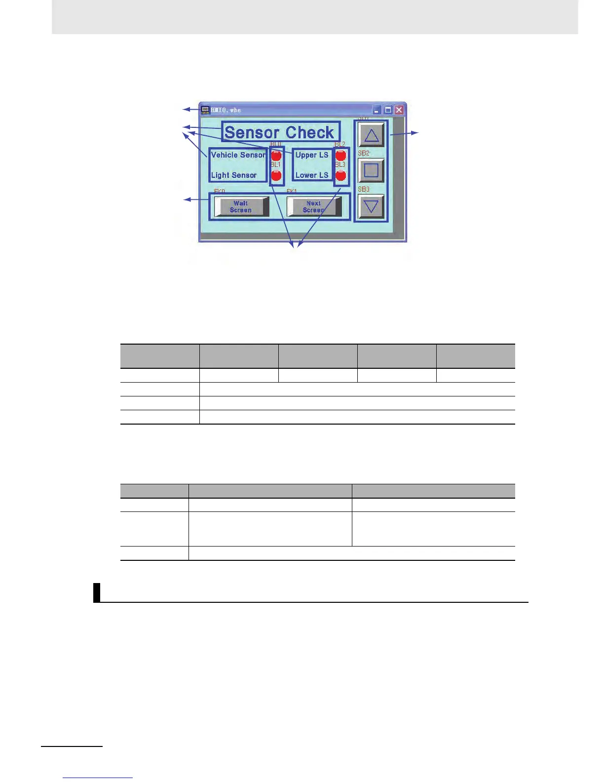
The whole screen is shown below. The creating methods for fixed text and Bit State Setting
components for [Open], [Stop] and [Close] garage door operations are the same as that of [1 Wait].
a Screen b Fixed Texts c Bit State Lamp d Function Keys e Bit State Setting components
z Bit State Lamp
The states of the vehicle sensor, light sensor, upper LS and lower LS are shown by the lamp.
The attribute settings for the Bit State Lamp are:
z Function Key Components
These are used for switching to [1 Wait] and [7 Check 2] screens.
The attribute settings of the Function Key components are:
The [7 Check 2] screen will appear after the screen-switching button on [6 Check 1] or
[8 Check 3] screen is pressed.
Configure functions below:
• Fixed text indicating the garage door state.
• Bit State Lamp components activating relevant lamp to check operations when the [OPEN], [STOP]
or [CLOSE] Function Key turns ON.
• Function Key component, a button for switching to [6 Check 1] and [8 Check 3] screens.
• Bit State Setting components, allocated to [Open], [Stop] and [Close] garage door operations
respectively.
Corresponding
Name
Vehicle Sensor Light Sensor Upper LS Lower LS
Read Address CIO 0.03 CIO 0.04 CIO 0.05 CIO 0.06
Function Normal
Tag Do not use
Graphics Use the vector graphic: Lamp2State1-00.vg
Screen Name Wait Screen Next Screen
Function Key Switch to base window [1 Wait] Switch to base window [7 Check 2]
Tag Use tags:
0: Wait Screen
1: Wait Screen
Use tags:
0: Next Screen
1: Next Screen
Graphics Use the vector graphic: CTRL_BAR001.vg
[7 Check 2]
a
b
d
e
c
 Loading...


