A-11
Appendices
NB-series Programmable Terminals Setup Manual(V107)
A-4 Fabrication of the Connection Cable
App
A-4-4 Method for Fabricating the Cable for
Connection to OMRON PLC
.
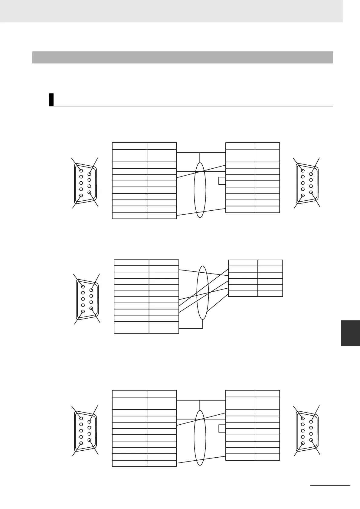
When fabricating the cable for connecting the NB Unit and OMRON PLC, refer to the following
methods:
The cable for connecting the NB3Q Unit serial port COM1 to OMRON PLC
(RS-232C)
The cable for connecting the NB3Q Unit serial port COM1 to OMRON PLC
(RS-422A)
Note If the RS-485 connection is adopted, all needed to do is to connect the No.6 and No.8 pins and the shielded
cable to the corresponding pins on the PLC side.
The cable for connecting the NB5Q/NB7W/NB10W Unit serial port COM1 to
OMRON PLC (RS-232C)
A-4-4 Method for Fabricating the Cable for Connection to OMRON PLC
COM1
COM1 (female)
at the NB Unit side
NB Unit side
Shielded Cable
OMRON PLC side
Signal Name Pin No.
Connector
Shield
FG
SDB+ 1
2
3
4
5
6
7
8
9
SD(TXD)
RD(RXD)
RS(RTS)
CS(CTS)
RDB+
SDA-
RDA-
SG
1
5
6
9
1
5
6
9
RS232 port at the
OMRON PLC side
(female)
Pin No.
1
2
3
4
5
6
7
8
9
Signal Name
FG
SD
RD
RS
CS
5V
NC
NC
SG
COM1 (female)
at the NB Unit side
NB Unit side
Shielded Cable
Signal Name Pin No.
SDB+
SD(TXD)
RD(RXD)
2
3
1
4
5
6
7
8
9
RS(RTS)
RDA-
CS(CTS)
RDB+
SDA-
SG
FG
Connector
Shield
1
5
6
9
OMRON PLC side
Pin No.
1RDA-
RDB+
SDA-
SDB+
FG
2
3
4
5
Signal Name
COM1 (female)
at the NB Unit side
NB Unit side
Shielded Cable
OMRON PLC side
Signal Name Pin No.
Connector
Shield
FG
NC 1
2
3
4
5
6
7
8
9
SD
RD
RS(RTS)
CS(CTS)
DC+5V
NC
NC
SG
1
5
6
9
1
5
6
9
RS232 port at the
OMRON PLC side
(female)
Pin No.
1
2
3
4
5
6
7
8
9
Signal Name
FG
SD
RD
RS
CS
5V
DR
ER
SG
WWW.NNC.IR

 Loading...


