A-13
Appendices
NB-series Programmable Terminals Setup Manual(V107)
A-4 Fabrication of the Connection Cable
App
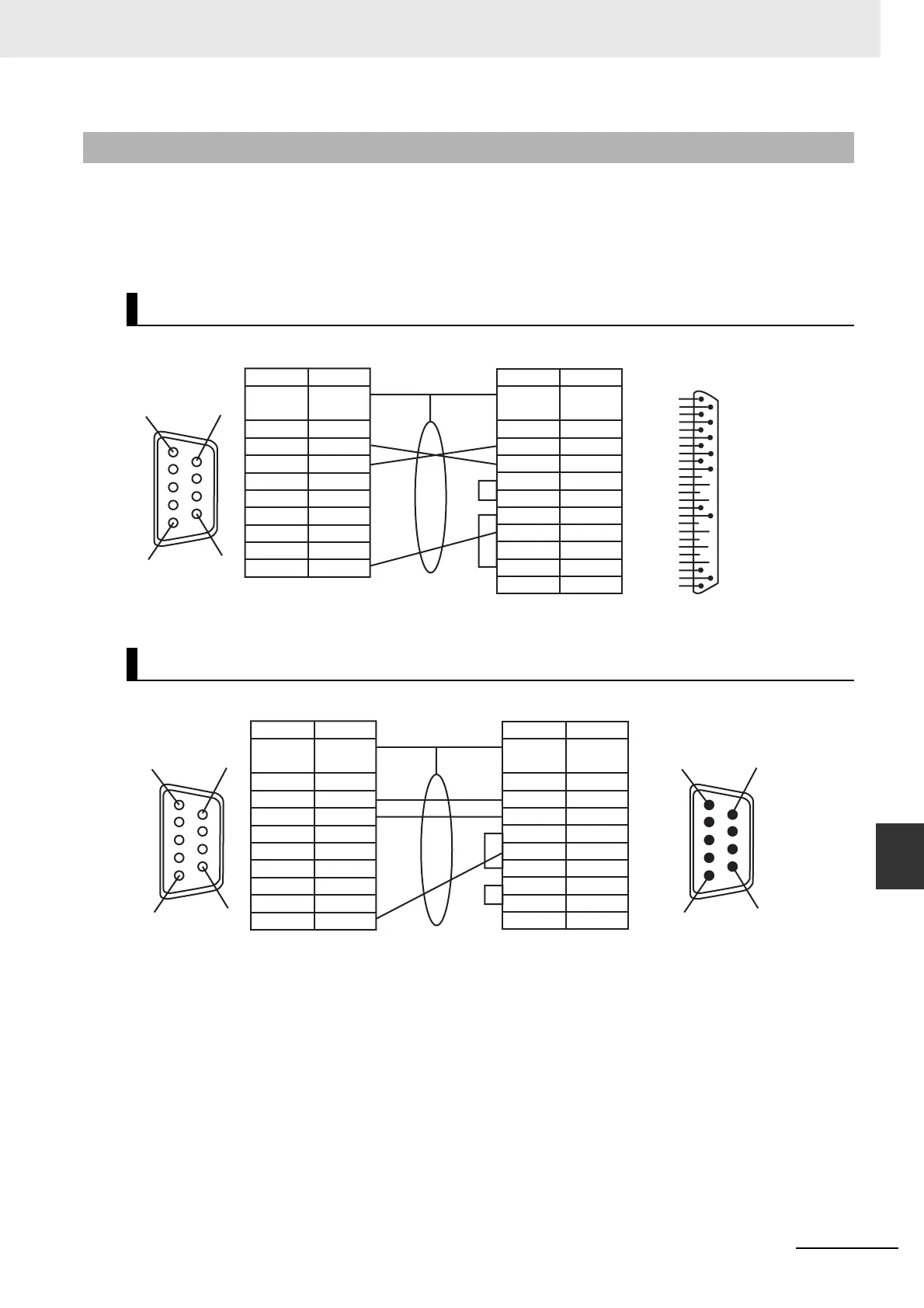
A-4-5 Method for fabricating the cable for
connection to PC
When fabricating the cable for connecting with NB-Designer, refer to the following methods:
Depending on the type of the RS-232C connector compatible with PCs according to DOS/V, deploy the
wiring as shown below:
Note As to the 2 connection methods introduced above, the No.2, 3 and 9 pins of COM1 on the NB3Q unit side
have the same definitions as those described in the above diagram, and the method for connection to a PC
is also the same as above.
A-4-5 Method for fabricating the cable for connection to PC
25-pin Connector
9-pin Connector
13
25
14
1
COM1 (female)
at the NB Unit side
NB Unit side
Shielded Cable
DB25 Serial Port at the PC side
RS232 DB25 (male)
at the PC side
Signal Name Signal Name
Pin No. Pin No.
FG
Connector
Shield
Connector
Shield
FG
NC
SD
RD
RS (RTS)
CS (CTS)
DC+5V
NC
NC
SG
6
7
8
9
4
5
3
2
1
1
2
3
4
5
6
7
8
20
22
FG
SD
RD
RS
CS
DR
SG
CD
ER
RI
1
5
6
9
COM1 (female)
at the NB Unit side
NB Unit side
Shielded Cable
DB9 Serial Port at the PC side
RS232 DB9 (male)
at the PC side
Signal Name Signal Name
Pin No. Pin No.
FG
Connector
Shield
Connector
Shield
FG
NC
SD
RD
RS (RTS)
CS (CTS)
DC+5V
NC
NC
SG
6
7
8
9
4
5
3
2
1
1
2
3
4
5
6
7
8
9
CD
RD
SD
ER
SG
DR
RS
CS
RI
1
5
6
9
5
1
9
6
WWW.NNC.IR

 Loading...


