2-74
Note 1. Function allocations for pin 40 to 46 sequence inputs and pin 25 to 30 sequence outputs can
be set by means of user parameters Pn50A to Pn50D, Pn513, and Pn50E to Pn510, respec-
tively. The allocations shown in this table are the defaults.
Note 2. Do not wire the empty pins.
Note 3. When an absolute encoder is used, connect the battery (2.8 to 4.5 V) to the backup battery
inputs at pins 21 and 22 or to CN8 (Battery Connector).
D CN1 Connectors (50P)
Servo Driver receptacle 10250-52A2JL (Sumitomo 3M)
Cable solder plug 10150-3000VE (Sumitomo 3M)
Cable case 10350-52A0-008 (Sumitomo 3M)
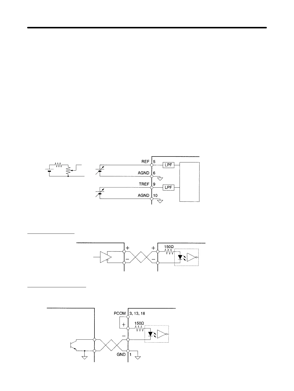
H Control Input Circuits
D Speed and Torque Command Inputs
(When analog controls are used.)
470 Ω (1/2 W max.)
12 V DC
2 kΩ (1/2 W max.)
Speed command
Torque command
Servo Driver
Converter
Input impedance: Approx. 14 kΩ
Circuit time constant: Approx. 47 µs
Maximum input voltage: 12 V
D Position Command Pulse Inputs and Deviation Counter Reset Inputs
Line Driver Input
Controller Servo Driver
Applicable line driver:
AM26L S31A or equivalent
Input current:10 mA, 3 V
Open Collector Input
Using Power Supply for Open Collector Commands (PCOM)
Controller
Servo Driver
Input current: 10 mA, 12 V
Signal levels
High (H): 2.4 V min.
Low (L): 0.8 V max.
Standard Models and Specifications Chapter 2
 Loading...


