2-85
Note 2. With the default allocation, the function for pin 41 is changed to MING, PLOCK, TVSEL, RDIR,
or IPG according to the Pn000.1 (control mode selection) setting and the control mode in op-
eration. For details, refer to 4-4-3 Important Parameters.
D Pulse Disable Input (41: IPG)
Command pulse inputs are disabled. The motor will stop when this signal goes ON, and the position will
be locked.
Note 1. This is the default allocation. Input terminal allocations (CN1 pins 40 to 46) can be changed by
setting Pn50A.0 (input signal selection mode) to 1. The IPG signal is allocated by Pn50d.1.
Note 2. With the default allocation, the function for pin 41 is changed to MING, PLOCK, TVSEL, RDIR,
or IPG according to the Pn000.1 (control mode selection) setting and the control mode in op-
eration. For details, refer to 4-4-3 Important Parameters.
D Gain Switching Input (Not Allocated: GSEL)
The GSEL signal changes the gain. When this signal is not input, the settings of Pn100 (speed loop
gain), Pn101 (speed loop integration constant), and Pn102 (position loop gain) are used for control.
When this signal is input, the settings of Pn104 (No. 2 speed loop gain), Pn105 (No. 2 speed loop in-
tegration constant), and Pn106 (No. 2 position loop gain) are used for control.
Note The GSEL signal is not allocated by default. Input terminal allocations (CN1 pins 40 to 46) can be
changed by setting Pn50A.0 (input signal selection mode) to 1. The GSEL signal is allocated by
Pn50d.2.
D Command Pulse Factor Switching Input (Not Allocated: PSEL)
The PSEL signal changes the command pulse factor.
When this signal is not input, the command pulse is used to rotate the motor.
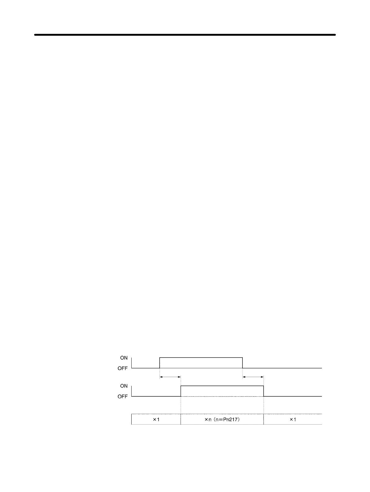
When this signal is input, the result of applying the settings of Pn217 (command pulse factor) to the
command pulse is used to rotate the motor. The PSON (command pulse factor enable) output, which
indicates that the command pulse factor has changed, turns ON.
The ON/OFF timing for the PSEL signal and PSON signal is shown in the following diagram.
Note 1. When the command pulse factor change function is used, set Pn218.0 (command pulse fac-
tor switching function selection) to 1, and set the applicable factor in Pn217.
Note 2. Allocate the PSON signal using Pn510.2.
Command pulse factor
switching input (PSEL)
Command pulse factor
enabled output (PSON)
Internal operation
4 ms max. 4 ms max.
Note The PSEL signal is not allocated by default. Input terminal allocations (CN1 pins 40 to 46) can be
changed by setting Pn50A.0 (input signal selection mode) to 1. The PSEL signal is allocated us-
ing Pn513.0.
Standard Models and Specifications Chapter 2

 Loading...


