2-86
H Control Output Details
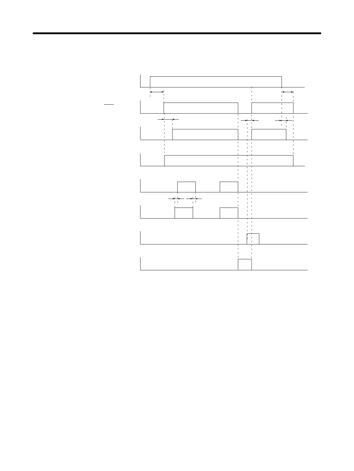
D Control Output Sequence
Power supply input
(L1C, LC2, L1, L2, (L3))
Alarm output
(ALM
)
Brake interlock output
(BKIR)
RUN command input
(RUN)
Alarm reset input
(RESET)
Alarm code outputs
(ALO1, ALO2, ALO3)
ON
OFF
ON
OFF
ON
OFF
ON
OFF
ON
OFF
ON
OFF
ON
OFF
ON
OFF
2 ms0 to 35 ms
200 ms (See note.)
300 ms
2ms 60ms
Servo ready output
(READY)
Positioning completed output 1, 2
(INP1, INP2)
Approx. 2 s
Note This signal will remain ON for approximately 250 ms after input of the SEN signal when using an
absolute encoder.
D Encoder A-, B-, Z-phase Outputs
33: +A; 34: –A; 36: +B; 35: –B; 19: +Z; 20: –Z
D 48: +ABS, 49: –ABS
Servomotor encoder signals are output as divided phase-difference pulses according to the encoder
dividing rate setting (Pn201). The output form is line driver output, and conforms to EIA-RS-422A. Re-
ceive the signals with a line driver or high-speed photocoupler.
By inputting the SEN signal (low to high), absolute data is first output as serial data from the phase A,
and then it is output as A-phase and B-phase initial incremental pulses (90° phase-difference pulses).
The output operation is the same as for an ordinary incremental encoder (90° phase-difference pulses).
Standard Models and Specifications Chapter 2

 Loading...


