3-36
H Leakage Current and Leakage Breakers
Use a surge-resistant leakage breaker designed for Inverters that will not operate for high-frequency
currents. The detection current of a leakage breaker is set to approximately 60% of the normal rated
current. You should thus allow a leeway of approximately two times the rated current.
Leakage current will also flow to the input noise filter, switch mode power supply, and other devices. Be
sure to allow for these devices as well.
Values indicated with asterisks are measured using the UL (JIS) methods.
Servo Driver
model
*Leakage current
(for 10-m cable)
*Additional leakage
current per 10 m of cable
PWM
frequency
Input power supply
voltage
R88D-WTA3HL
2.5 mA 0.5 mA 11.7 kHz Single-phase
R88D-WTA5HL
100/115 VAC (85 to
R88D-WT01HL
127
,
50
60
z
R88D-WT02HL 3.0 mA
R88D-WTA3H
5.0 mA
R88D-WTA5H
R88D-WT01H
R88D-WT02H
8.0 mA
R88D-WT04H
R88D-WT05H
R88D-WT08H
R88D-WT10H
10.0 mA 0.6 mA 3.9 kHz Single-phase
R88D-WT15H
200/230 VAC (170 to
R88D-WT20H
12.0 mA 0.7 mA
253
,
50
60
z
R88D-WT30H
R88D-WT50H 15.0 mA 0.8 mA
R88D-WT60H
21.0 mA 1.0 mA
R88D-WT75H
R88D-WT150H 57.0 mA 1.5 mA
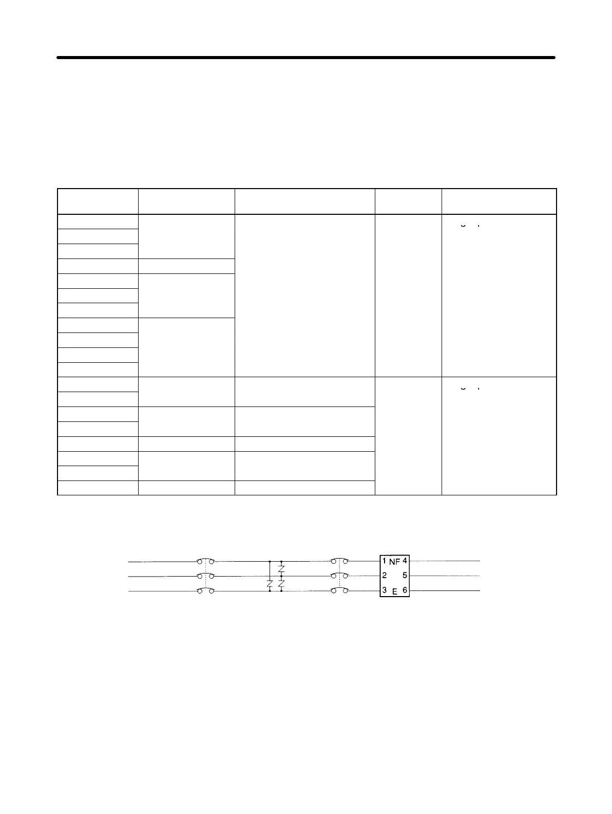
Leakage Breaker Connection Example
AC power
supply side
No-fuse
breaker
Surge
absorber
Leakage
breaker
Noise
filter
Servo Driver
side
H Improving Encoder Cable Noise Resistance
The OMNUC W Series uses serial encoders, with phase-S signals from the encoder. The phase-S com-
munications speed is 4 Mbits/s.
In order to improve the encoder’s noise resistance, take the following measures for wiring and installa-
tion.
• Always use the specified Encoder Cables.
• If lines are interrupted in the middle, be sure to connect them with connectors, making sure that the
cable insulation is not peeled off for more than 50 mm. In addition, always use shielded cable.
System Design and Installation
Chapter 3

 Loading...


