6-8
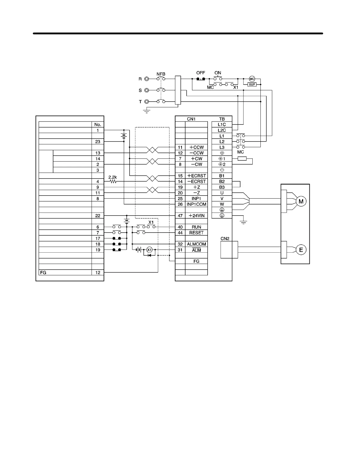
H Connection Example 7: Connecting to SYSMAC
C200H-NC211/C500-NC113/211 Position Control Units
R88D-WTj
R88M-Wj
Encoder Cable
R88A-CRWj
R88A-CRWjR
Power Cable
R88A-CAWj
R88A-CAWjR
Red
White
Blue
Green/
Yellow
Class-3 ground
Noise filter
Main circuit power supply
24 V DC
C200H-NC211
C500-NC113/211
200/230 V AC 50/60Hz
Contents
CW (with a resistor)
CW (without a resistor)
CCW (with a resistor)
CCW (without a resistor)
0-V DC power (for output)
X-axis pulse
output
X-axis dev. cntr. reset output
X-axis origin line driver input
X-axis origin common
X-axis positioning completion input
X/Y-axis input common
X-axis external interrupt input
X-axis origin proximity input
24-V DC input (for output)
X-axis CCW limit input
X-axis CW limit input
X/Y-axis emerg. stop input
Main circuit contact
Surge killer
Shell
DC reactor
24 V DC
24 V DC
Note 1. The example shows a 3-phase, 200-V AC input to the Servo Driver for the main circuit power
supply. Be sure to provide a power supply and wiring conforming to the power supply specifi-
cations for the Servo Driver in use.
Note 2. Incorrect signal wiring can cause damage to Units and the Servo Driver.
Note 3. Leave unused signal lines open and do not wire them.
Note 4. Use mode 2 for origin search.
Note 5. Use the 24-V DC power supply for command pulse signals as a dedicated power supply.
Note 6. The diode recommended for surge absorption is the ERB44-02 (Fuji Electric).
Note 7. This wiring diagram is for the X axis only. If the other axis is to be used, connect to the Servo
Driver in the same way.
Note 8. Make the setting so that the Servo can be turned ON and OFF with the RUN signal.
Appendix Chapter 6

 Loading...


