6-12
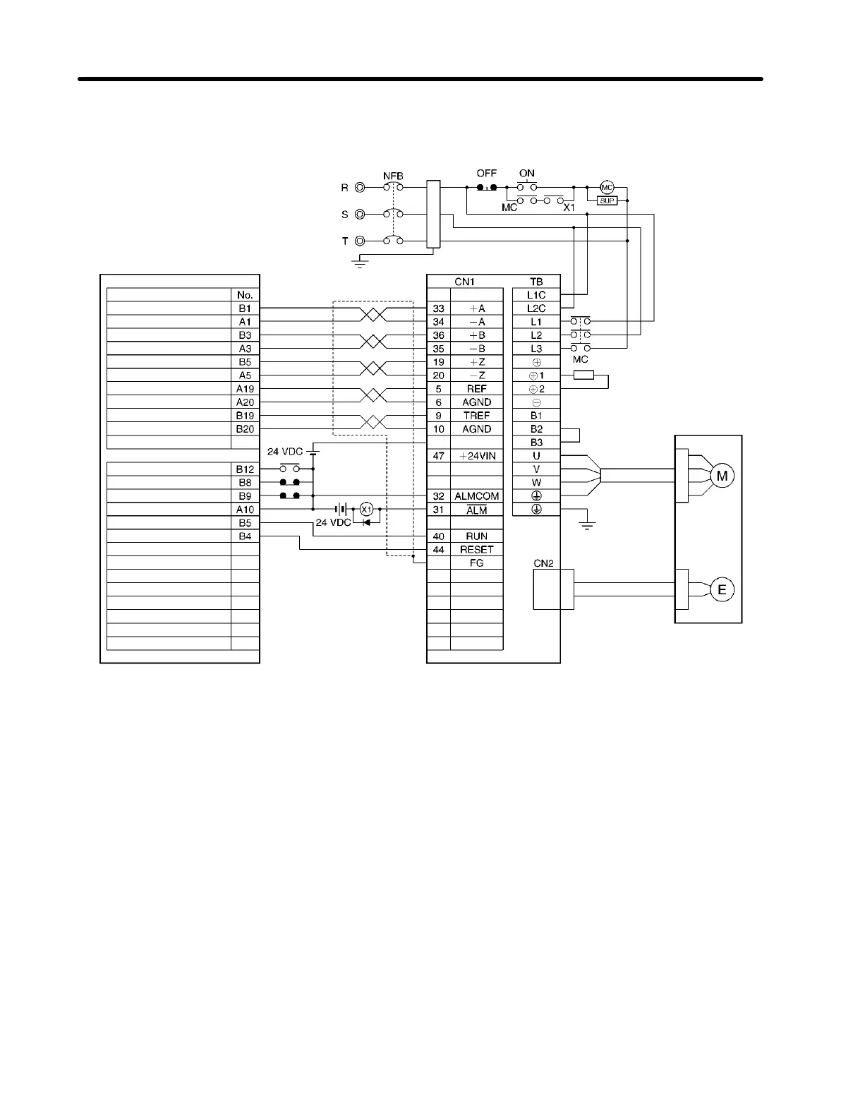
H Connection Example 11: Connecting to a SYSMAC CS1W-HCA12/22-V1
Customizable Counter Unit
Main circuit power supply
3-phase 200/230 V AC 50/60 Hz
Class-3 ground
Main circuit contact
Surge killer
R88D-WTj
Noise filter
CS1W-HCA12/22-V1
DC reactor
Power Cable
R88A-CAWj
R88A-CAWjR
R88M-Wj
Encoder Cable
R88A-CRWj
R88A-CRWjR
Red
White
Blue
Green/
Yellow
Alarm reset *
Special I/O connector
Name
Phase-A LD+
Phase-A LD–
Phase-B LD+
Phase-B LD–
Phase-Z LD+
Phase-Z LD–
Analog output 1 (+)
Analog output 1 (–)
Analog output 2 (+)
Analog output 2 (–)
I/O connector
Origin proximity input signal*
CCW limit input signal*
CW limit input signal*
Common (for input)
Servo ON*
Shell
Note 1. Incorrect signal wiring can cause damage to Units and the Servo Driver.
Note 2. Leave unused signal lines open and do not wire them.
Note 3. Use the 24-V DC power supply for command pulse signals as a dedicated power supply.
Note 4. The diode recommended for surge absorption is the ERB44-02 (Fuji Electric) or equivalent.
Note 5. Do not share the 24-V DC power supply for the break with the 24-V DC power supply for con-
trol.
* The I/O signals of the CS1W-HCP22-V1 depend on the internal memory area allocations. Change the
wiring according to the allocations.
Appendix Chapter 6
 Loading...


