38 SmartController EX User's Guide 11069-000 Rev. H
4.5 Connecting User-Supplied Safety and Power-Control Equipment
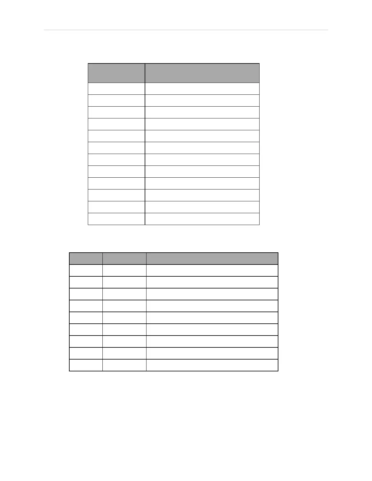
Table 4-8. Remote Pendant Connections on the XMCP Connector
Pin XMCP
(15-Pin D-Sub)
Description
1, 9 Pendant E-Stop Push-button CH 1
2, 10 Pendant E-Stop Push-button CH 2
3, 11 Pendant Enable CH 1 (Hold-to-run)
4, 12 Pendant Enable CH 2 (Hold-to-run)
13 Serial GND / Logic GND
7 Pendant TXD: “eV+to Pendant TXD”
8 Pendant RXD: “eV+to Pendant RXD”
14 No connection
15 No connection
Shield Shield GND
6 24 V
5 No connection
Table 4-9. XSYS Connector Pin Assignments
Pin Signal Description
1 ESTOPGND GND Return
2 MANUAL1 Manual Mode ESTOP Ckt. CH 1
3 MANUAL2 Manual Mode ESTOP Ckt. CH 2
4 HIPWRDIS High Power Disable
5 HIPWRREQ High Power Request
6 AUTO1 Auto Mode ESTOP Ckt. CH 1
7 AUTO2 Auto Mode ESTOP Ckt. CH 2
8 N/C No Connection
9 ESTOPSRC 24 V Output to Slave ESTOP
NOTE: The XSYS connector is used to link the E-Stop system to our robots. It is
not intended for customer connections.