123
IR SR HR TR AR LR TC DM #
00000 to 23515 23600 to 25507 HR 0000 to 9915 TR 0 to 7 AR 0000 to 2715 LR 0000 to 6315 TC 000 to 511 Read/Wr: DM 0000 to DM 0999
Rd only: DM 1000 to DM 1999
0000 to 9999
or 0000 to FFFF
These footnote tables show the actual ranges of all data areas. Bit numbers are provided (except for DM and TC areas); remove the rightmost two digits for word numbers.
Data
Areas
Appendix E
Programming Instructions
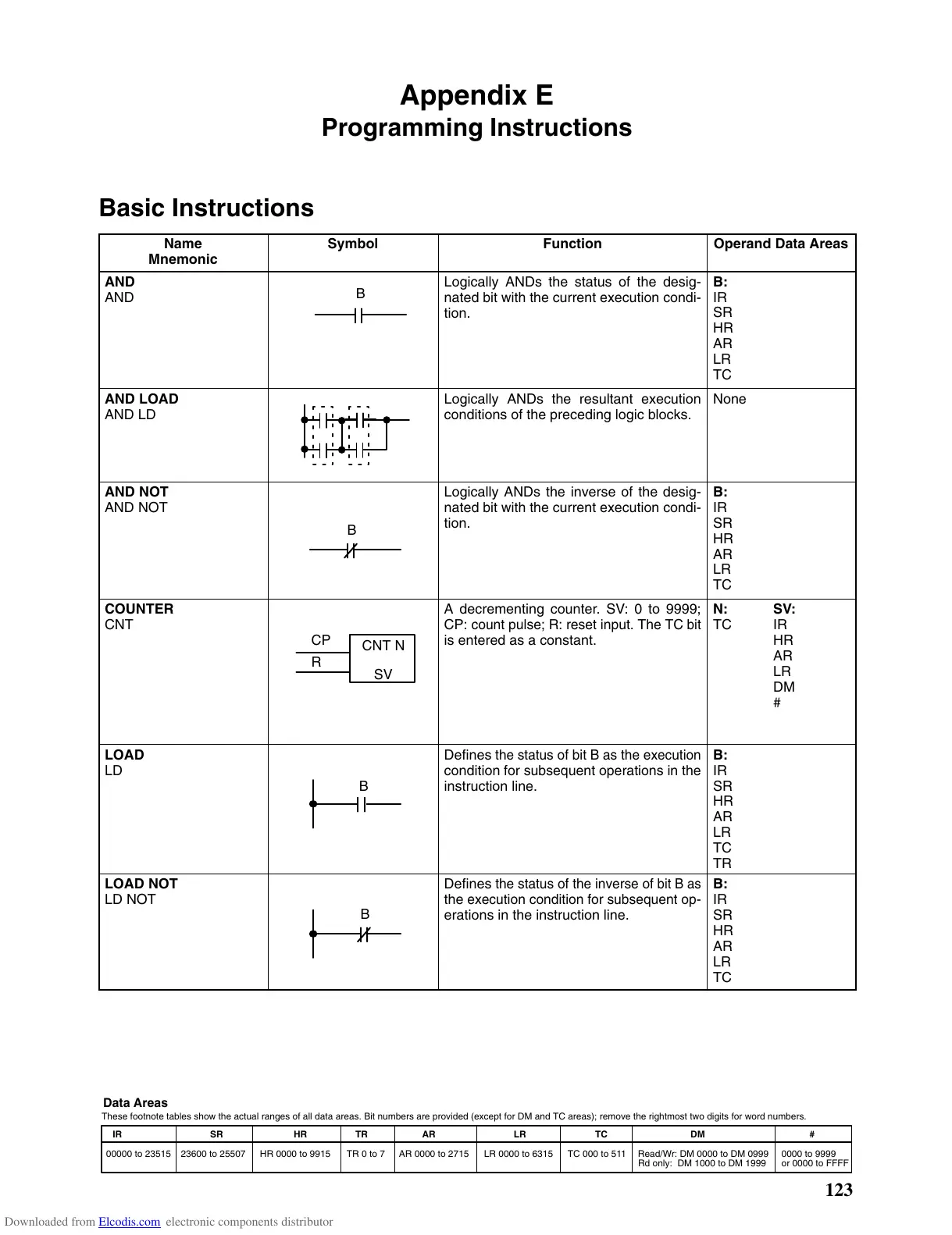
Basic Instructions
Name
Mnemonic
Symbol Function Operand Data Areas
AND
AND
B
Logically ANDs the status of the desig-
nated
bit with the
current execution condi
-
tion.
B:
IR
SR
HR
AR
LR
TC
AND LOAD
AND LD
Logically ANDs the resultant execution
conditions of the preceding logic blocks.
None
AND NOT
AND NOT
B
Logically ANDs the inverse of the desig-
nated
bit with the
current execution condi
-
tion.
B:
IR
SR
HR
AR
LR
TC
COUNTER
CNT
CNT N
SV
CP
R
A decrementing counter. SV: 0 to 9999;
CP:
count pulse; R: reset input. The TC
bit
is entered as a constant.
N:
TC
SV:
IR
HR
AR
LR
DM
#
LOAD
LD
B
Defines
the
status of bit B as the execution
condition
for subsequent operations in the
instruction
line.
B:
IR
SR
HR
AR
LR
TC
TR
LOAD NOT
LD NOT
B
Defines
the status of the inverse of
bit B as
the
execution condition for subsequent op
-
erations in the instruction line.
B:
IR
SR
HR
AR
LR
TC
Downloaded from Elcodis.com electronic components distributor